CDU Operating & Maintenance Guide Page 35
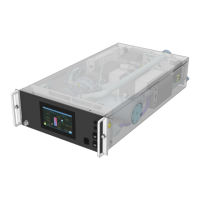
Neptune DWC RM100 in-rack Coolant Distribution Unit
Pump 1 has not reached the differential pressure (or flow rate) setpoint and is running at 100% in the
specified time limit (default 30 secs). Pump 1 will then stop and Pump 2 will run.
Check that unit has been set for the correct system flow rate (or DP), check for system blockages,
check speed controller for faults, check non-return valve on Pump 2 is not sticking open. Reduce flow
setting (or DP).
Pump 2 has not reached the differential pressure (or flow rate) setpoint and is running at 100% in the
specified time limit (default 30 secs). Pump 2 will then stop and Pump 1 will run.
Check that unit has been set for the correct system flow rate (or DP), check for system blockages,
check speed controller for faults, check non-return valve on Pump 1 is not sticking open. Reduce flow
setting (or DP).
MicroSD card has reached capacity
2.7 Temperature Sensor Graph
The chart above may be used to check the validity of any of the temperature sensors used in the unit or
the remote room sensor.
32 37 42 47 52 57 62 67 72 77 82 87 92 97 102 107 112 117 122 127 132 137
0
2
4
6
8
10
12
14
16
18
20
22
24
26
28
30
32
34
0 5 10 15 20 25 30 35 40 45 50 55 60
Temperature (
o
F)
Resistance (k
Ω)
Temperature (
o
C)
Temperature Sensor Resistance Graph
Fig.23 – Temperature Sensor Resistance Graph
 Loading...