EasyManua.ls Logo

Lenovo Neptune DWC RM100 - DIAGNOSTICS Screen; Fig.12 - Control System Diagnostics Screen

Lenovo Neptune DWC RM100
51 pages
To Next Page IconTo Next Page
To Previous Page IconTo Previous Page
Loading...
CDU Operating & Maintenance Guide Page 20
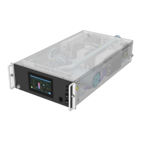
Neptune DWC RM100 in-rack Coolant Distribution Unit
2.2.10 DIAGNOSTICS Screen
This screen will give raw information and conversion factors for the status for all Universal Inputs,
Resistive Inputs, Digital Inputs, Digital Outputs, and Analogue Outputs.
I/O Diagnostics Universal Inputs 1 to 8
ID
Description
ADC Value
Electrical
Processed
UI01
Secondary Flow Temp. T2a
0
0
Ohms
0.00
degC
UI02
Secondary Flow Temp. T2b
0
0
Ohms
0.00
degC
UI03
Secondary Flow Temp. T2c
0
0
Ohms
0.00
degC
UI04
Secondary Return Temp. T4
0
0
Ohms
0.00
degC
UI05
Secondary Return Pressure PS1
0
0.00
mA
0.00
bar
UI06
Pump Inlet Pressure PS2
0
0.00
mA
0.00
bar
UI07
Secondary Supply Pressure PS3
0
0.00
mA
0.00
bar
UI08
Room Sensor RH
0
0.00
mA
0.00
%
I/O Diagnostics Universal Inputs 9 to 14
ID
Description
ADC Value
Electrical
Processed
UI09
Ambient Sensor Temperature T3
0
0.00
mA
0.00
degC
UI10
Primary Flow Temperature T1
0
0.00
mA
0.00
degC
UI11
Primary Flow Rate
0
0.00
mA
0
l/m
UI12
Secondary Flow Rate
0
0.00
mA
0
l/m
UI13
Control Valve Feedback
0
0.00
V
0.00
%
UI14
Primary Return Temperature T5
0
0
Ohms
0.00
degC
I/O Diagnostics Resistive Inputs 1 to 4
ID
Description
ADC Value
Electrical
Processed
RI01
RI02
Leak Tape - CDU
0
0
Ohms
0
RI03
Leak Tape External Primary
0
0
Ohms
0
RI04
Leak Tape External Secondary
0
0
Ohms
0
I/O Diagnostics Digital Inputs 1 to 6
ID
Description
State
DI01
Optical Level Sensor
0
DI02
Drive Status
0
DI03
DI04
DI05
DI06
I/O Diagnostics Digital and Analogue Outputs
ID
Description
State
DO01
Fill Pump
0
DO03
Pump Cooling Fan
0
DO04
Alarm Output
0
AO04
Cooling Valve
%
Fig.12 Control System Diagnostics screen

Table of Contents

Related product manuals