CDU Operating & Maintenance Guide Page 16
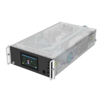
Neptune DWC RM100 in-rack Coolant Distribution Unit
2.2.8 CONFIGURATION Screen
The Configuration screen can be used to set specific parameters and control functions.
NOTICE! Parameter ID’s shown in ‘red’ text will only be accessible with the Engineer
log-in code.
Start threshold for fill pump
Stop hysteresis for fill pump
Time for level sensor to make, or fill pressure to
be satisfied, prior to alarm (when unit is on-line)
Level Senor response time, prior to alarm
Delay prior to pump start after initiate signal
Fill Warning Delay Period
Delay prior to ‘check make-up’ alarm activated
Select Manual or Automatic Fill pump control
0 = Manual; 1 = Automatic
Configuration – Pump Control
Select pump speed controlled by flow or DP
Set the required Secondary flow rate
Differential Pressure Setpoint
Set the required Secondary differential
pressure (DP)
Low flow alarm threshold (% of flow setpoint)
Time delay prior to low Flow/DP alarm
Set minimum pump running speed
Maximum system pressure, prior to alarm
Alarm only, or shutdown & alarm
Initial pump start fixed speed (0 = Auto)
Initial start speed hold period, prior control
loop taking over
Scan period for pump speed control loop
Maximum pump speed control loop pressure
DP Setpoint – Max Cooling
Mode
DP Setpoint used when operating in Max
Cooling mode
Cooling Fan Run On Period
The period of time the fan will run on for after
the unit is switched to standby
Fig.10 – Control System Configuration screen
 Loading...