3.3.7 Fluid checks .................................................................................................................... 37
3.3.8 Functional checks ............................................................................................................ 37
3.4 Secondary Filter Service ..................................................................................................... 38
3.5 Spare Parts ........................................................................................................................ 38
4. Additional Information ............................................................................................................... 40
4.1 Wiring Diagram (WD00003-01) ............................................................................................ 40
4.2 Pipe Schematic (SC00002-01) ............................................................................................. 47
4.3 Warranty & Contact Details .................................................................................................. 49
Figures
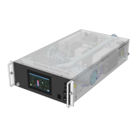
Fig.1 – Front View of RM100 .......................................................................................................... 8
Fig.2 – Rear View of RM100 (with hose connection detail) ...................................................... 9
Fig.3 – Control System Home Screen ............................................................................................ 10
Fig.4 – Control System main Menu Screen ............................................................................... 11
Fig.5 – Control System Status Screen ............................................................................................ 11
Fig.6 – Control System Data Curves Screen ............................................................................... 13
Fig.7 – Control System Alarms Screen ............................................................................................ 13
Fig.8 – Control System Log-in Screen ............................................................................................ 14
Fig.9 – Control System Setup Screen ............................................................................................ 14
Fig.10 – Control System Configuration Screen ............................................................................... 16
Fig.11 – Control System Service Screen ............................................................................................ 18
Fig.12 – Control System Diagnostics Screen ............................................................................... 20
Fig.13 – Control System Calibration Screen ............................................................................... 21
Fig.14 – Control System On/Off Button ............................................................................................ 21
Fig.15 – Fill Required Warning ......................................................................................................... 21
Fig.16 – Fill Pump Manual Activation ............................................................................................ 22
Fig.17 – Fill Pressure & Level Flow Chart (at initial start) .................................................................. 22
Fig.18 – Fill Pressure & Level Flow Chart (when running) .................................................................. 23
Fig.19 – Water Level Management Flow Chart (when running) ..................................................... 24
Fig.20 – Control System Alarm Indication ............................................................................... 27
Fig.21 – Control System Active Alarms ............................................................................................ 28
Fig.22 – Control System Alarm Identification ............................................................................... 28
Fig.23 – Temperature Resistance Chart ............................................................................................ 34
Fig.24 – Servicing Secondary Filter ............................................................................................ 36
 Loading...
