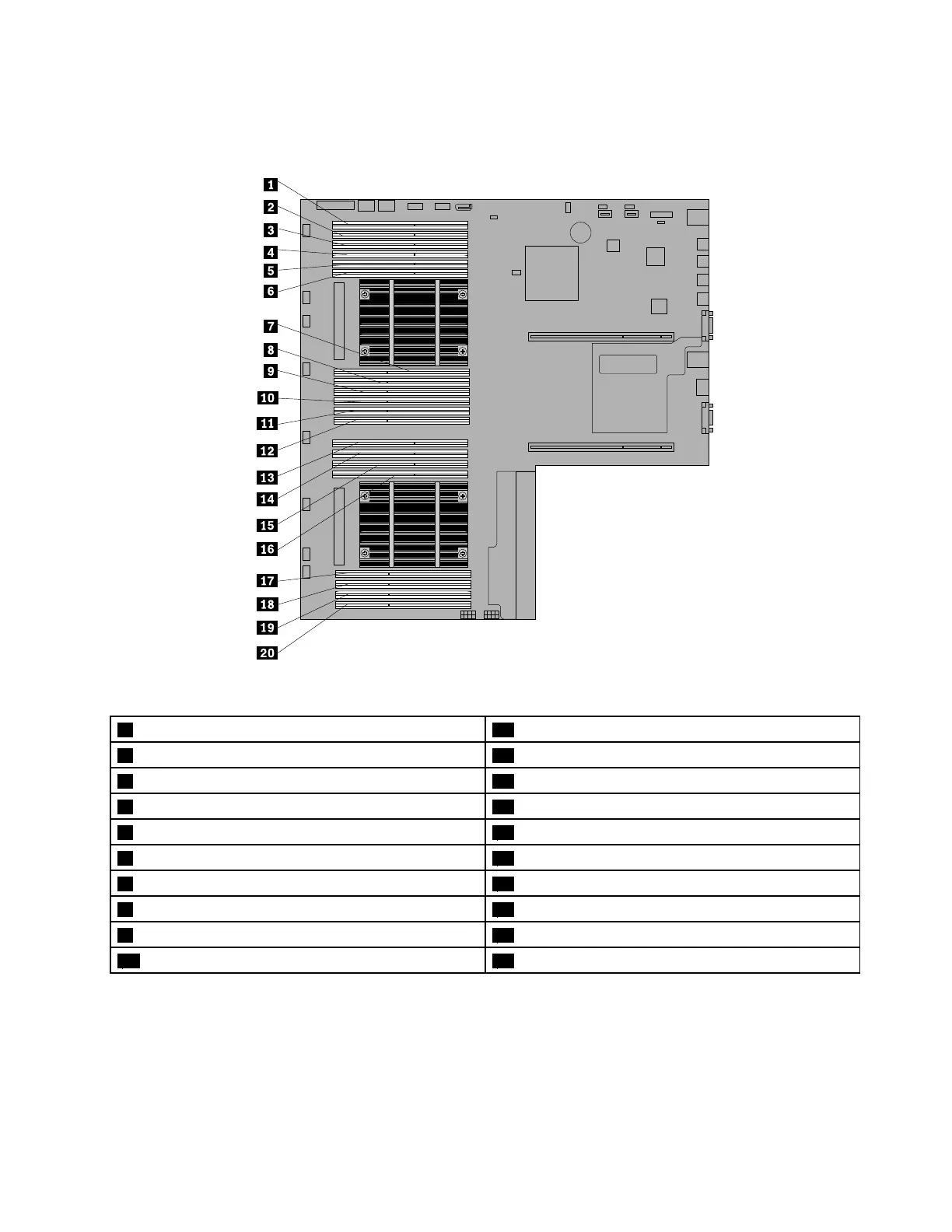
Thefollowingillustrationhelpsyoutolocatethememoryslotsonthesystemboard.Thefollowingillustration
showsthesystemboardwithtwoinstalledmicroprocessors(alsoknownasCPU)andtwoheatsinks.
Figure47.Memoryslotsonthesystemboard
1Memoryslot(CPU1DIMMC1)11Memoryslot(CPU1DIMMA2)
2Memoryslot(CPU1DIMMC2)12Memoryslot(CPU1DIMMA1)
3Memoryslot(CPU1DIMMC3)13Memoryslot(CPU2DIMMC1)
4Memoryslot(CPU1DIMMD1)14Memoryslot(CPU2DIMMC2)
5Memoryslot(CPU1DIMMD2)15Memoryslot(CPU2DIMMD1)
6Memoryslot(CPU1DIMMD3)16Memoryslot(CPU2DIMMD2)
7Memoryslot(CPU1DIMMB3)17Memoryslot(CPU2DIMMB2)
8Memoryslot(CPU1DIMMB2)18Memoryslot(CPU2DIMMB1)
9Memoryslot(CPU1DIMMB1)19Memoryslot(CPU2DIMMA2)
10Memoryslot(CPU1DIMMA3)20Memoryslot(CPU2DIMMA1)
Thefollowingtableprovidesinformationaboutthememorymoduleinstallationrulesforserversthathave
onlyonemicroprocessor(CPU1)installed.The“X”markindicatesthememoryslot(s)intowhichthememory
module(s)shouldbeinstalledindifferentsituations.
Note:Theinstalledmemorymodulesmustbethesametypewiththesamerank,voltage,andfrequency.
Chapter6.Installing,removing,orreplacinghardware87