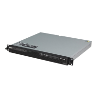
The CD or DVD drive is attached to an ATA 100 signal cable. The blue connector
is attached to the system board. The connector on the other end is attached to
the master IDE device. The middle connector attaches to an optional optical
device or tape drive.
v Simple-swap SATA (TD100 models only): The combination signal/power cable
connects to the system board and simple-swap backplate to provide signal and
power to the simple-swap SATA drives.
Simple-swap SATA models include a combination signal/power cable connected
to the system board and the simple-swap SATA backplate.
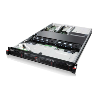
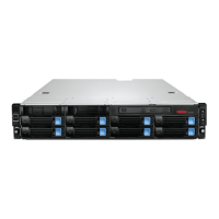
v Hot-swap SAS or hot-swap SATA: Hot-swap SAS and hot-swap SATA models
come with a single signal cable and a single power cable that connects to the
system board and the hot-swap SAS/SATA backplane to provide signal and
power to the SAS or SATA drives. For TD100, If you order the 4-drive backplane
option kit to upgrade to eight drives, the option kit comes with an additional
signal cable and power cable.
Note: When you install the optional 4-drive backplane option kit to upgrade to
eight drives, make sure that you remove the dust shield (if one is present) from
the hot-swap SAS/SATA signal connector on the system board. Carefully grasp
the dust shield and pull it out of the signal connector.
For
more information about the requirements for SAS cable and connecting SAS
devices, see the documentation that comes with these devices.
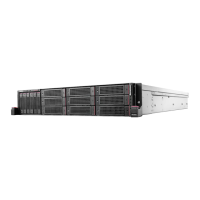
For a list of supported options for the server, see http://www.lenovo.com/
thinkserver/.
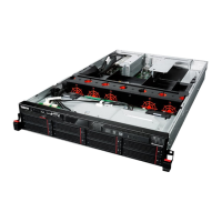
Installing an adapter
The following notes describe the types of adapters that the server supports and
other information that you must consider when installing an adapter. The type of
adapters that the server supports might vary, depending on your server model.
v Locate the documentation that comes with the adapter and follow those
instructions in addition to the instructions in this section. If you must change the
switch setting or jumper settings on the adapter, follow the instructions that come
with the adapter.
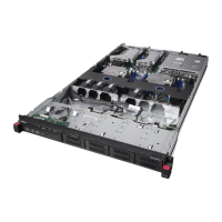
v The server comes with the following adapter connectors, or slots:
– Slot 1, PCI Express x8 (x4)
Important: The x8 (x4) designation for slot 1 identifies an x8 slot that is
designed to support x4 adapters and x8 adapters that can downshift to
operate at the x4 bandwidth. If you install an x8 adapter in slot 1 that can
downshift to the x4 bandwidth, it will run at the x4 bandwidth. The x8
connector can be used for x4 and x8 adapters. Check the information that
comes with your adapter for compatibility information.
– Slot 2, PCI Express x8 (x8)
– Slot 3, PCI Express x8 (x8)
– Slot 4, PCI-X 64-bit/133 MHz
– Slot 5, PCI-X 64-bit/133 MHz
– Slot 6, PCI 32-bit/33 MHz
v
You can install supported full-length adapters in slots 2, 3, 4 and 5. You can
install only half-length adapters in slots 1 and 6.
v Universal adapters are supported in slots 4 and 5 if they are universally keyed.
40 ThinkServer TD100 and TD100x Types 4203, 4204, 4205, 4206, 6398, 6399, 6419, and 6429: User Guide
 Loading...