Installation
4-7
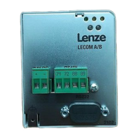
L _^ONMObk
PC/PLC
T/R/(A)
T/R/(B)
PE
71 72 88
89
2102
Controller
1
2102
Controller
2
71 72 88
Fig. 4-5 Connection to the host (PC/PLC)
Connection between two controllers (cable 1 in Fig. 4-4):
• Connect the cable shield with terminal 89 (direct PE) of one fieldbus module and terminal 88
(capacitive PE) of the other fieldbus module (Fig. 4-5).
This method prevents currents flowing through the cable screens.
• Connect the terminals 71 and 72 between the fieldbus modules via paired cables (e.B. green
and yellow).
Direct connection to the host (cable 2a in Fig. 4-4)
• Connect the host cable screen to PE and the controller cable screen to terminal 88.
This method prevents currents flowing through the cable screens.
Connection to the 201IB interface converter (cable 2b in Fig. 4-4):
PC/PLC
PE
71 72 88
89
2102
Controller
1
2102
Controller
2
71 72 88
89
RxD
TxD
71
72
88
2101IB interf a ce converter
Fig. 4-6 Connection to the 2101IB interface converter
• Connect the cable shield with terminal 89 (direct PE) of the last controller and terminal 88
(capacitive PE) of the interface converter (Fig. 4-6).
This method prevents currents flowing through the cable screens.
Buy: www.ValinOnline.com | Phone 844-385-3099 | Email: CustomerService@valin.com