CANopen
4 Installation
4-3
L BA2175 EN 2.0
4.3 Electrical installation
Note!
The communication of 820X and 821X controllers can be interfered by electromagnetic
interferences.
If necessary, use an additional PE shield cable at position 6
(^ 4-1)
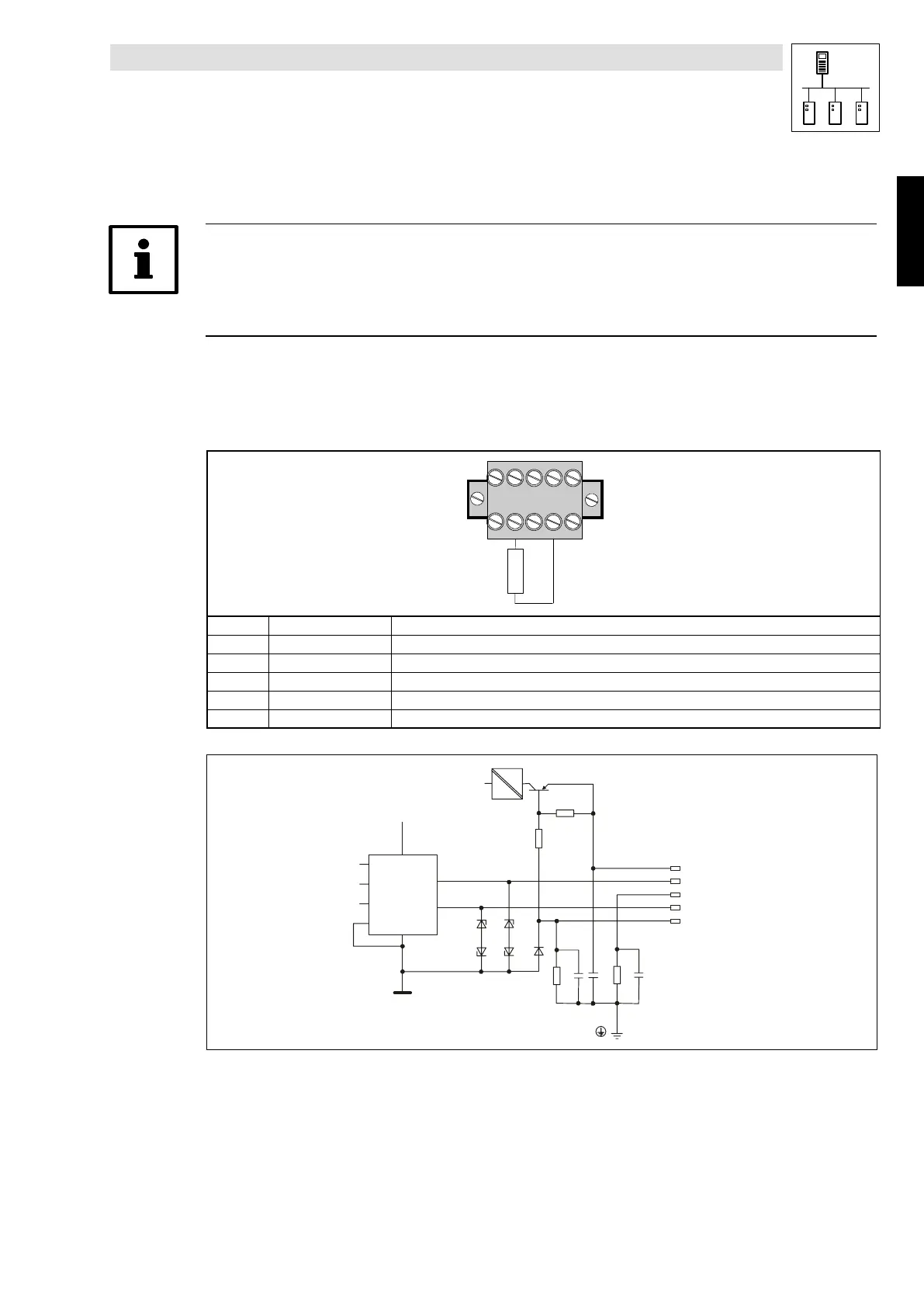
4.3.1 Assignment of the plug/socket connector
The 2175 fieldbus module is connected to the bus througha5poleplug/socketconnector.
54321
2175
120R
Terminal Designation Explanation
1 V- GND; reference for external voltage supply
2 CAN_L Data cable / input for terminating resistance of 120 Ohm
3 SHIELD Shield
4 CAN_H Data cable / input for terminating resistance of 120 Ohm
5 V+ External voltage supply; see notes in chapter 10.3.3
2175DeN007
+Vcc
+V
cc
+V
CAN+
Shield
CAN-
-V
7
6
2
8
5
3
1
4
DC
DC
Fig. 4-1 Terminal assignment
Phone: 800.894.0412 - Fax: 888.723.4773 - Web: www.actechdrives.com - Email: info@actechdrives.com