Electrical installation
Wiring of the feedback system
Resolver at X7
5
211
EDKVS9332X DE/EN/FR 8.0
5.10.2 Resolver at X7
Technical data
Field Values
Connection at drive controller Connector: Socket, 9−pole, Sub−D
Resolver type recommended Receiver
Number of pole pairs of the resolver 1
Transmission ratio 0.3
Evaluation method Voltage impression in the sine and cosine winding
Max. output voltage ± 10 V
Max. current consumption 50 mA per winding
Max. impedance [Z] 500 W per winding
Output frequency 4 kHz
Monitoring Monitoring for open circuit of the resolver and the resolver cable
(configurable)
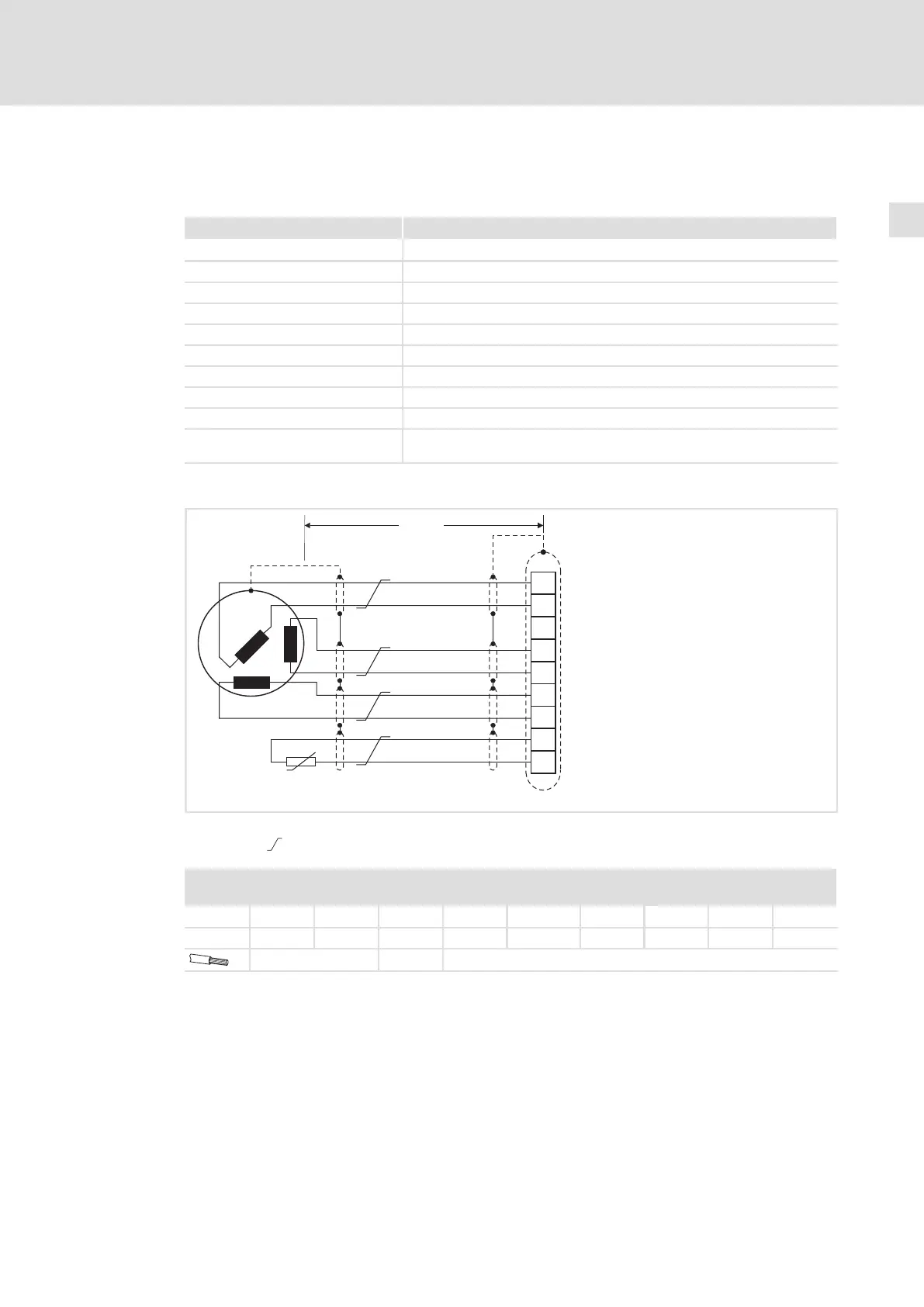
Wiring
+REF
-REF
+COS
+SIN
-SIN
-COS
+KTY
-KTY
1
2
3
4
5
6
7
8
9
X7
<50m
KTY
9300STD331
Fig. 5−32 Resolver connection
Cores twisted in pairs
X7 − Resolver
Connector: Socket, 9−pole, Sub−D
Pin 1
2 3 4 5 6 7 8 9
Signal +REF −REF GND +COS −COS +SIN −SIN +KTY −KTY
0.5 mm
2
(AWG 20) ˘ 0.14 mm
2
(AWG 26)
 Loading...


