Free connection of analog signals
Free configuration analog process data output words
10
Function library
10.12
10.12.3
L
10.12-12
EDS82EV903-1.0-11/2002
Code IMPORTANTPossible settings
No. SelectionLenzeName
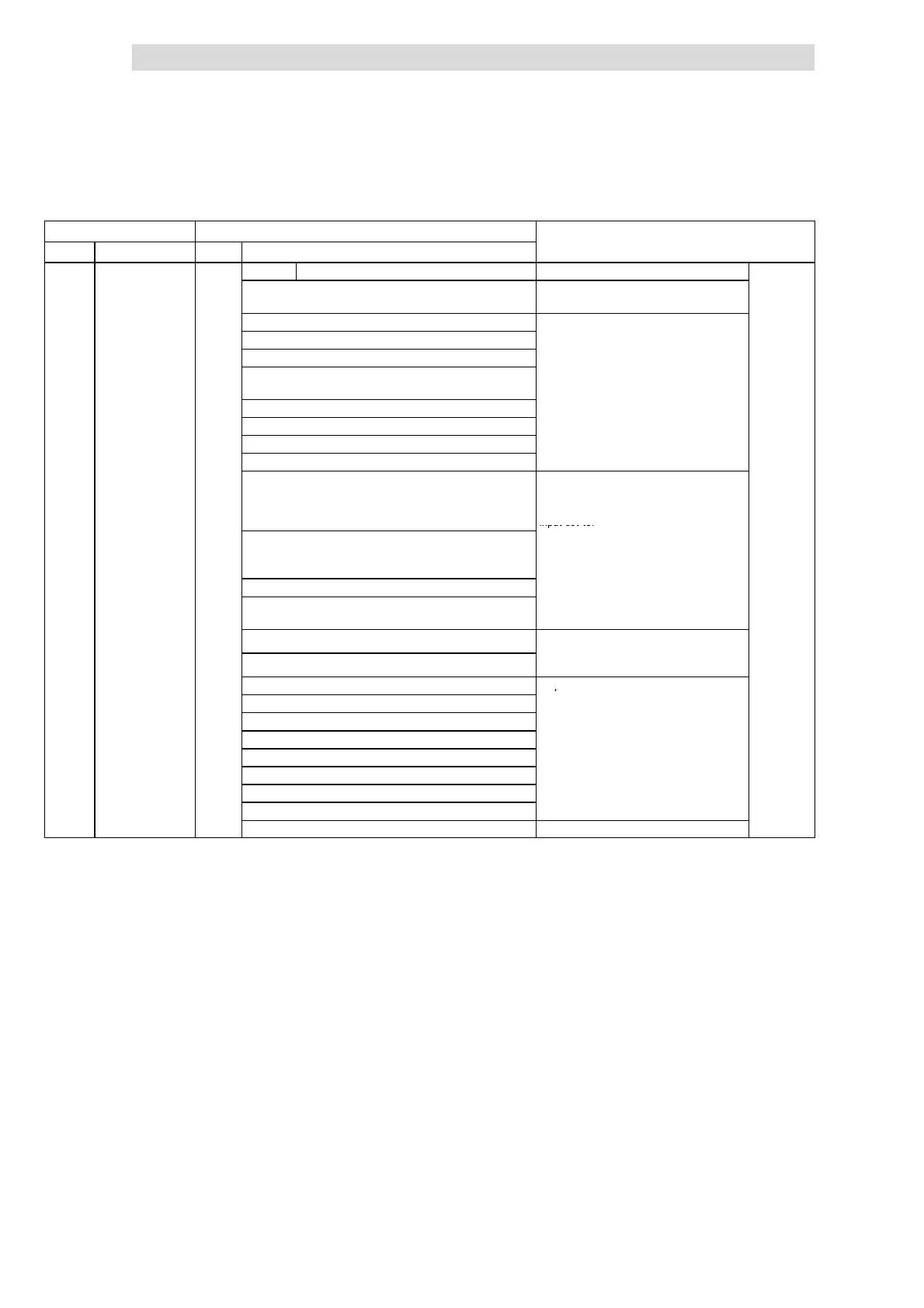
C0421* Possible analog sig nals for C0421 ^
v
(cont.)
26 Output frequency normalised without s lip
(MCTRL1-NOUT-NORM)
2
14
≡ C0011
10.12-10
27 Output frequency without slip (MCTRL1-NOUT)
24000 ≡ 480 Hz
28 Act. process controller value (PCTRL1-ACT)
29 Process controller setpoint (PCTRL1-SET1)
30 Process controller output without precontrol
(PCTRL1-OUT)
31 Ramp function generator input (NSET1-RFG1-IN)
32 Ramp function generator output (NSET1-NOUT)
33 (A ) PID controller output (PCTRL1-PID-OUT)
34 (A ) Process controller output (PCTRL1-NOUT)
35 Input signal at X3/8 (Standard-I/O) or X3/1U or
X3/1I (Application-I/O), evaluated with gain
(C0414/1 or C0027) and offset (C0413/1 or
C0026) (AIN1-OUT)
1000 ≡ Maximum value analog input signal
(5 V, 10 V, 20 mA, 10 kH z)
Condition: Gain of analog input or frequency
input set to:
36 Input signal at frequency input X3/E1,
evaluated with gain (C0426) and offset (C0427)
(DFIN1-OUT)
C0414/x, C0426 = 20/C0011 [%]
37 Motor potentiometer output (MPOT1-OUT)
38 (A ) Input signal at X3/2U or X3/2I, evaluated with
gain (C0414/2) a nd of fset (C0413/2) (AIN2-OUT)
40 AIF input word 1 (AIF-IN.W1)
Setpoint to drive from communication
41 AIF input word 2 (AIF-IN.W2)
mo
u
e
o
Normalisation via AIF
50 CAN-IN1.W1 or FIF-IN.W1
Setpoints to drive from function module to
51 CAN-IN1.W2 or FIF-IN.W2
FIF
52 CAN-IN1.W3 or FIF-IN.W3
Normalisation via C
NorFIF
53 CAN-IN1.W4 or FIF-IN.W4
60 CAN-IN2.W1
61 CAN-IN2.W2
62 CAN-IN2.W3
63 CAN-IN2.W4
255 Not assigned (FIXED-FREE)
The process data output words are linked with internal analog signals by entering
the selection figure of the internal signal in the corresponding subcode of C0421.
C0421 can be different for the parameter sets.
Signal linkage
 Loading...


