Code table
10
Function library
10.20
L
10.20-9
EDS82EV903-1.0-11/2002
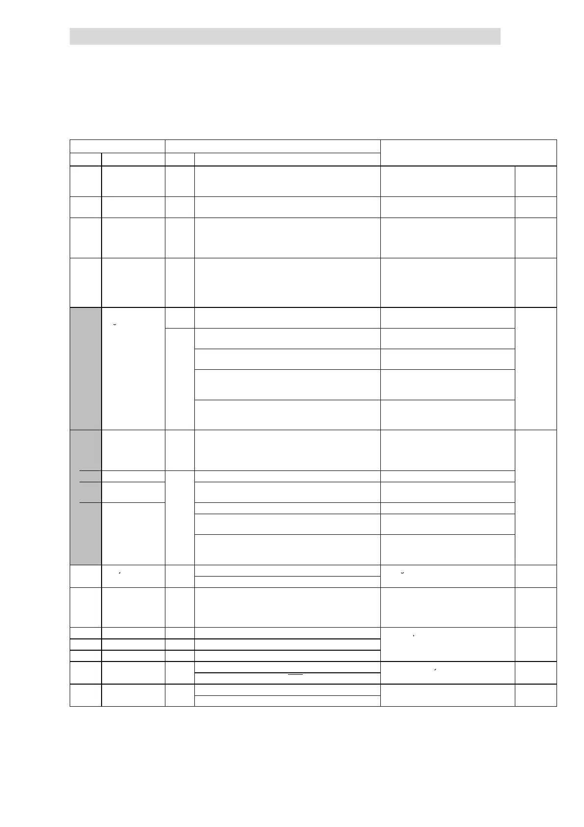
Code IMPORTANTPossible settings
No. SelectionLenzeName
C0022 I
max
limit (motor
mode)
150 30 {1 %} 150 Only 8200 vector 15 ... 90 kW:
If C0022 = 150 %, 180 % I
r
are available
for max. 3 s. after controller enable
^ 10.6-3
C0023 I
max
-limit in the
generator mode
150 30 {1 %} 150 C0023 = 30 %: function is inactive, if
C0014 = 2, 3:
^ 10.6-3
C0026* Offset analog input
1 (AIN1–OFFSET)
0.0 -200.0 {0.1 %} 200.0 • Settings for X3/8 and X3/1U, X3/1I
• The max. limit of t he setpoint value
range o f C0034 e quals 100 %
• C0026 and C0413/1 are identical
^ 10.8-3
C0027* Gain analog input 1
(AIN1-GAIN)
100.0 -1500.0 {0.1 %} 1500.0 • Settings for X3/8 and X3/1U, X3/1I
• 100.0 % = Ga i n 1
• Inverse setpoint selection by negative
gain and negative offset
• C0027 and C0414/1 are identical
^ 10.8-3
C0034* Setpoint selection
range
Observe the switch position of the function
module!
^ 10.8-3
v
uSEr
Standard–I/O (X3/8)
61
0
0 Unipolar voltage 0 ... 5 V / 0 ... 10 V
Current 0 ... 20 mA
1 Current 4 ... 20 mA Changing the direction of rotation is only
possible with a digital signal.
2 Bipolar voltage -10 V ... +10 V • Minimum output frequency (C0010) not
effective
• Individual adjustment of offset and gain
3 Current 4 ... 20 mA open-circuit monitored TRIP S d5, if I < 4 mA
Changing the direction of rotation is only
possible with a digital signal.
C0034*
v
(A)
uSEr
Setpoint selection
range
Applicat ion I/O
Observe the jumper setting of the function
module!
^ 10.8-3
1 X3/1U, X3/1I
0
0 Unipolar voltage 0 ... 5 V / 0 ... 10 V
2 X3/2U, X3/2I 1 Bipolar voltage -10 V ... +10 V Minimum output f re quency (C0010) not
effective
2 Current 0 ... 20 mA
3 Current 4 ... 20 mA Changing the direction of rotation is only
possible with a digital signal.
4 Current 4 ... 20 mA open-circuit monitored Changing the direction of rotation is only
possible with a digital signal.
TRIP Sd5 if I < 4 mA
C0035* DC injection brake 0
0 Brake voltage selection under C0036
Holding time ð C0107 ^ 10.7-6
v
(DCB) control mode
1 Brake current selection under C0036
C0036 Voltage/current DC
injection brake
(DCB)
à 0.00 {0.01 %} 150.00 % à Depending on the controller
• Reference M
r
,I
r
• Setting applies to all mains voltages
permitted
^ 10.7-6
C0037 JOG1 20.00 -650.00 {0.02 Hz} 650.00
JOG = Setpoint ^ 10.8-13
C0038 JOG2 30.00 -650.00 {0.02 Hz} 650.00
Additional JOG frequencies ð C0440
C0039 JOG3 40.00 -650.00 {0.02 Hz} 650.00
C0040* Controller inhibit
-0- controller inhibited (CINH)
Controller can only be enabled if X3/28 = ^ 10.5-3
v
(CINH)
-1- Controller enabled (CINH)
HIGH
C0043* TRIP reset
0 No current error
Reset active error with C0043 = 0
v
1 Active fault