Safety engineering
Device modules
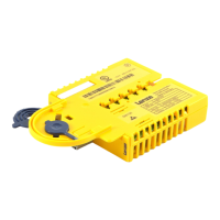
SM302 safety module
1
22
EDS94AYAF EN 1.0
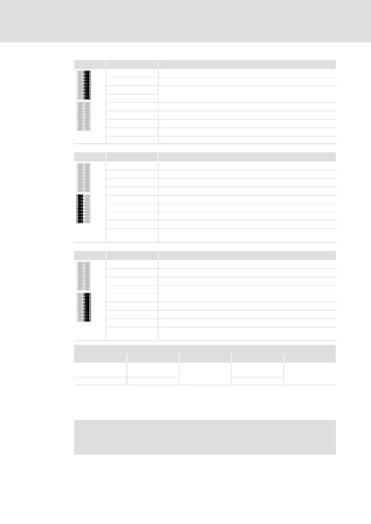
X82.2 Labelling Description
−
GND external supply
+
+24 V external supply via a safely separated power supply unit (SELV/PELV)
GIR
This part of the terminal strip is reserved.
RI1
GO
GND 24O
24O
+24 V external supply for the safe monitor SD−Out1 (SELV/PELV)
AIE
Error acknowledgement input ("Acknowledge In Error")
CLA Clock output for passive sensors, channel A (Clock A)
CLB Clock output for passive sensors, channel B (Clock B)
X82.3 Labelling Description
GCL
GND clock output
GI2
GND SD−In2
I2B
Sensor input SD−In2, channel B
I2A
Sensor input SD−In2, channel A
GCL
GND clock output
GI1
GND SD−In1
I1B
Sensor input SD−In1, channel B
I1A
Sensor input SD−In1, channel A
AIS
Restart acknowledgement input ("Acknowledge In Stop", 1−channel,
bridged to X82.4/AIS)
X82.4 Labelling Description
GCL
GND clock output
GI4
GND SD−In4
I4B
Sensor input SD−In4, channel B
I4A
Sensor input SD−In4, channel A
GCL
GND clock output
GI3
GND SD−In3
I3B
Sensor input SD−In3, channel B
I3A
Sensor input SD−In3, channel A
AIS
Restart acknowledgement input ("Acknowledge In Stop", 1−channel,
bridged to X82.3/AIS)
Cable cross−sections and tightening torques
Type [mm
2
] [Nm] AWG [lb−in]
Wire end ferrule,
insulated
0.25 ... 0.75
Spring terminal
24 ... 18
Spring terminal
Rigid
0.14 ... 1.5 26 ... 16
Stripping length or contact length: 9 mm
Insulated wire end ferrules according to DIN 46228, part 4, 0.5 mm
2
or 0.75 mm
2
− length
L1 = 10 mm can be used.
Note!
Provide for a sufficient strain relief, so that the terminals are not pulled from
the plug connectors, in particular when you use rigid cables.