Safety engineering
Safety functions
Cascading
1
58
EDS94AYAF EN 1.0
GO
24O
GO
O1B
O1A
GI4
I4B
I4A
-
+
X82.1 X82.2
X82.3
X82.4
24 V ext.
GO
24O
GO
O1B
O1A
GI4
I4B
I4A
-
+
X82.1 X82.2
X82.3
X82.4
24 V ext.
GO
24O
GO
O1B
O1A
GI4
I4B
I4A
-
+
X82.1 X82.2
X82.3
X82.4
24 V ext.
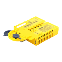
#1 #2 #n
SM302
E94AYAF
SM302
E94AYAF
SM302
E94AYAF
SSP94SM365 302
Fig. 1−11 Wiring example
E94AYAF SM302 safety module
#1, #2, #n Number of the module
24 V ext. 24−V voltage supply of the module (SELV/PELV)
24−V voltage supply of the output (SELV/PELV)
1.3.18.2 Conditions
ƒ The SD−In4 input must be parameterised as active input for the "emergency stop"
function and the input delay for SD−In4 must be £ 10 ms.
ƒ The emergency stop function to be executed must be parameterised as STO via the
"SSE: emergency stop function" parameter.
ƒ The restart behaviour of the drive after the STO/SS1 stop function has been
executed must be parameterised to "Acknowledged restart".
ƒ The control of the SD−Out1 output via a possibly parameterised safety bus must be
inhibited.
ƒ The SS1 mode (C15306) must be set to "STO after stopping time".
ƒ The plausibility check rejects other settings until they are parameterised correctly.