Leuze electronic BCL 8 3
Figures and tables
Figure 2.1: Example for the attachment of the sticky labels with warning notices..........................7
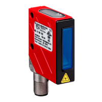
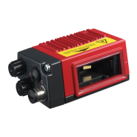
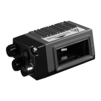
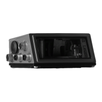
Figure 3.1: Device construction of the BCL 8.................................................................................8
Table 4.1: Technical data............................................................................................................10
Table 4.2: LED indicators............................................................................................................11
Figure 4.1: Dimensioned drawing BCL 8 S M …0, BCL 8 S N …0 with lateral beam exit ...........12
Figure 4.2: Dimensioned drawing BCL 8 S M …2, BCL 8 S N …2 with front beam exit..............13
Table 4.3: Type overview - M-optics ...........................................................................................14
Table 4.4: Type overview - N-optics............................................................................................14
Figure 4.3: Reading field of BCL 8 S M … with M-optics (medium density).................................15
Figure 4.4: Reading field of BCL 8 S N … with N-optics (high density)........................................16
Table 5.1: Accessories / order codes..........................................................................................17
Figure 5.1: Photo and dimensioned drawing of the MA 8.1 connector unit..................................18
Figure 5.2: Electrical connection MA 8.1......................................................................................19
Figure 5.2: MA 8.1 - Pin assignment PWR IN HOST/RS 232 ......................................................20
Figure 5.3: MA 8.1 - Pin assignment SW IN/OUT ........................................................................20
Figure 5.4: Connection of the switching input/output of the MA 8.1 .............................................21
Figure 5.5: MA 8.1 - Pin assignment BCL ....................................................................................22
Figure 5.6: Pin assignment MA 8-01 ............................................................................................23
Figure 5.7: MA 8-01 - Pin assignment PWR IN HOST/RS 485....................................................24
Figure 5.8: MA 8-01 - Pin assignment SW IN/OUT......................................................................25
Figure 5.1: Electrical connection MA 8-01....................................................................................26
Figure 5.9: MA 8-01 - Pin assignment BCL..................................................................................26
Figure 5.1: Termination of the RS 485 interface in the MA 8-01 ..................................................27
Figure 5.2: Mounting devices for the BCL 8 .................................................................................28
Figure 6.1: BCL 8 device name plate ...........................................................................................29
Figure 6.2: BCL 8 mounting example...........................................................................................30
Figure 6.3: Definition of the BCL 8 reading angles
.......................................................................31
Figure 6.4: BCL 8 pin assignment ................................................................................................32
Table 6.1: Wiring description BCL 8............................................................................................32
Figure 6.5: Switching input for BCL 8 connection version 1 (standard setting)............................33
Figure 6.6: Switching input for BCL 8 connection version 2 (setting "inverted")...........................33
Figure 6.7: Switching output BCL 8..............................................................................................34
Table 6.2: Line lengths................................................................................................................35
Figure 7.1: Barcode label "Service"..............................................................................................38
Figure 7.2: Connecting the RS 232 interface to a PC or terminal ................................................38
Figure 9.1: Installation window .....................................................................................................41
Figure 9.2: Installation directory ...................................................................................................42
Figure 9.3: BCL 8 configuration software .....................................................................................42
Figure 10.1: Decode tab.................................................................................................................43
Figure 10.2: Standard settings for the Properties window – Decode tab .......................................44
Figure 10.3: Output tab...................................................................................................................45
Figure 10.4: Control tab..................................................................................................................46
Figure 10.5: Host interface tab .......................................................................................................47
Figure 10.6:
Standard settings for the Properties window – Host interface tab..............................48
Figure 10.7: Reference code tab....................................................................................................49
Figure 10.8:
Sensor tab..................................................................................................................50
Figure 10.9: Laser tab ....................................................................................................................51
Figure 10.10: AutoReflAct Wizard ....................................................................................................52
Figure 10.11: Switch tab...................................................................................................................53
Figure 12.1: Example barcode label types .....................................................................................67
Buy: www.ValinOnline.com | Phone 844-385-3099 | Email: CustomerService@valin.com
 Loading...