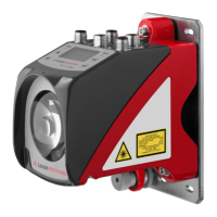
Electrical connection
Leuze electronic BPS 300i 45
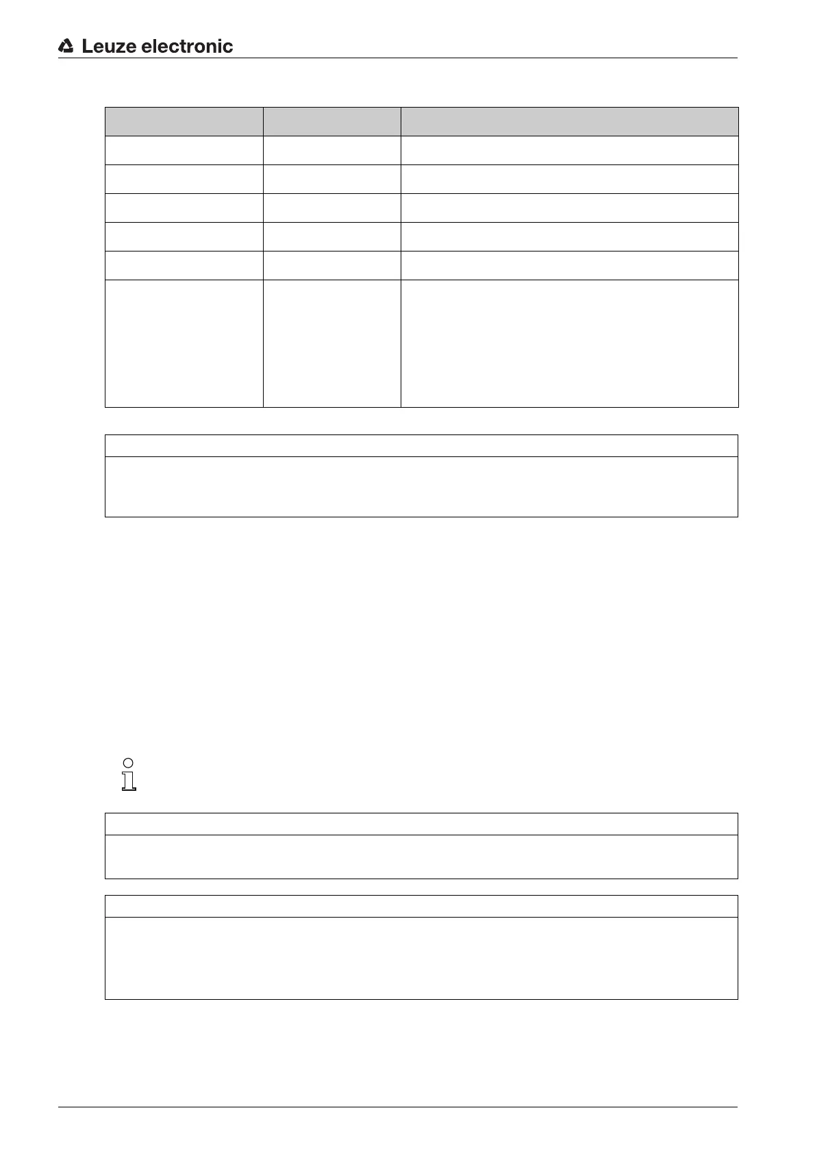
Table 7.1: PWR / SW IN/OUT pin assignment
Connection cables: see table 14.3
Switching input/output
The BPS is equipped with two, freely programmable, optically decoupled switching inputs/outputs, SWIO1
and SWIO2.
• The switching inputs can be used to activate various internal functions of the BPS (e.g., Measure-
ment Stop/Start, Teach Preset, Reset Preset).
• The switching outputs can be used to signal the state of the BPS and to implement external functions
independent of the superior control (e.g. position value/velocity value invalid, position and velocity
limit value exceeded, device error).
• The control can use switching inputs/outputs as digital I/Os.
If no internal BPS function is connected to the switching inputs/outputs, the ports can be addressed
as two inputs, two outputs or as one input and one output of a digital I/O component.
Pin/terminal Designation Assignment
1 VIN +18 … +30 VDC supply voltage
2 SWIO1 Sw. input/output 1 (configurable)
3 GNDIN Negative supply voltage (0 VDC)
4 SWIO2 Sw. input/output 2 (configurable)
5 FE Functional earth
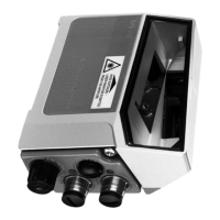
Thread (M12 plug)
Cable gland
Functional earth Connection cable shield.
The shield of the connection cable is on the thread of
the M12 plug or on the screw fitting of the cable bush-
ing.
The thread or the screw fitting is part of the metallic
housing. The housing is at the potential of the func-
tional earth via pin 5.
NOTICE
Attention!
For UL applications, use is only permitted in class 2 circuits in accordance with the NEC (National Elec-
tric Code).
The function as input or output is set via the webConfig configuration tool (CONFIGURATION >
DEVICE > Switching inputs/outputs, see chapter 9.3.2).
NOTICE
Maximum input current
The input current of the respective switching input is maximum 8 mA.
NOTICE
Maximum loading of the switching outputs
Do not load the respective switching output of the BPS with more than 60 mA at + 18 … 30 VDC in
normal operation.
Each configured switching output is short-circuit proof.