43
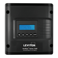
6.12 Installation Verication
Once the VerifEye
®
meter is congured and communicating with the RTU, it is
recommended to ensure that all the CTs are on the correct voltage phases and
that the CTs face the correct direction. Verify special circuit conditions, such as
unloaded motors, which may indicate an installation error when none exists. Use a
Digital Multimeter (DMM) to conrm.
6.12.1 Installation Phase Verication
The VerifEye
®
meter includes a PhaseChek™ algorithm that identies any
element that the meter suspects may be incorrectly phased (i.e., the CT is
associated with the wrong voltage source or is physically on the wrong wire)
based on power factors below 0.55. Use the LCD interface to access this
feature and navigate to VERIFY INSTALLATION and press ENTER. The
LCD display lists the elements that have at least one channel with a
low-power factor.
CHECK ELEMENTS
A EF
Use the navigation buttons to highlight a specic element and press ENTER,
or press ENTER and move from element to element using the <- / -> keys.
Within each element (identied on the top line of the display) the status of
each channel is identied as good (PF > 0.55) or bad (PF < 0.55).
ELEMENT F
CH1 Good
CH2 Bad
CH3 Bad
Two “Bad” channels are an indication that two CTs have been swapped.
When the power factor for all enabled channels is greater than 0.55, the
meter reports:
CHECK ELEMENTS
ALL CHANNELS GOOD
NOTE: PhaseChek is only applied for elements that are enabled. Use VIEW
METER SETUP on the LCD screen to ensure that all intended elements are
active. PhaseChek is advisory only. It is possible that the power factor for a
particular load is less than 0.55, as may be observed in a free-running motor.
The Power Meter Viewer Utilities software and the VerifEye® Web App run
PhaseChek continuously on all enabled elements and report low-power
factor in a real time values table by turning the text red, or by a using a
red indicator.
6 COMMUNICATION AND VERIFICATION