Page 7 of 32
User Guide
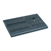
Leviton MC 7500 Series Memory Lighting Controllers
6. Scene Bump Buttons: These 16 (24) [32] buttons control the memory scene on the current page of memory.
These buttons can bring the scene to full intensity (normal bump mode), toggle the
scene OFF and ON (toggle mode), allow only one button to toggle at a time (kill mode),
or solo the scene by turning all other controller output OFF (solo mode). Fade will
work with all modes except normal bump mode.
7. Mode LEDs: These LEDs indicate whether the Scene B Sliders are in the Submaster, 1 - 16 (1
- 24) [1 - 32] (Scene B Mode), or 17 - 32 (25 - 48) [32 - 64] (wide mode). The Setup
and Mode function buttons under the LCD display change the operating mode. The
lit LED indicates the current mode.
8. BUMP MODE Button: This button controls the function of the Submaster Bump buttons. Pressing this button
cycles through the 4 operating modes: Toggle, Kill, Solo, and Momentary Bump. The
LEDs above indicate the current selection. When the LEDs are OFF, the Momentary
Bump mode is selected.
9. RECORD Button: This button is used to initiate recording of the submasters (memory scenes), Chases,
and the Cue Stacks. Programming is active when the Record LED is lit.
10. EDIT Button: This button is used to initiate editing of the submasters (memory scenes), Chases,
and the Cue Stacks. Editing is active when the Edit LED is lit.
11. PREVIEW Button: This button is used to select a memory scene on the current page to preview on the console
LEDs and LCD display. The Submaster Bump buttons are used to select the scene.
12. DIRECTION Button: This button and its respective LEDs controls the direction of the current chase selected
(has no effect on submaster chases or cue stack chases).
13. ATTACK Button: This button controls the fading between each chase step. The LEDs above indicate
the attack mode selected. A normal instant-ON instant-OFF mode is selected when
both LEDs are OFF.
14. TAP SYNC Button: Repeatedly pressing this button establishes the chase rate to be the time between
taps.
15. Chase Rate Slider: This control selects the chase rate for the entire controller.
16. CHASE SELECT Button: This button selects one of the possible chases to be active. The Submaster bump
buttons are used to select the chase number.
17. Chase Level Slider: This control sets the master level of only the selected chase. Submaster or stack
chases are not affected.
18. STACK GO Button: This button causes the next cue in stack sequence to execute when a stack is loaded.
19. Stack Crossfader: Used to manually crossfade the next scene in the Cue stack. When the control reaches
itʼs full up or down position, the next scene is loaded.
20. A Crossfader: This slider is used to proportionally vary the intensity of all of the Scene A sliders.
When the slider is at the top of itʼs travel, the control is at maximum. The LED above
the slider reflects the relative setting of the control.
21. B Crossfader: This slider is used to proportionally vary the intensity of all of the Scene B sliders. The
direction of travel for this slider is affected by the operating mode.
In the Two-Scene mode (B), the control is at maximum when the slider is at the bottom
of its travel. This provides easy split, dipless crossfading.
In the Submaster (SUBS) and Wide Mode (SNGL SCN or addition channels), the
control is at maximum when the slider is at the top of itʼs travel.
The LED above the slider reflects the relative setting of the control.