8
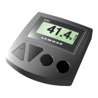
The panel must be installed in a dry location. The rear of the panel is not watertight, and must be protected
against water entry.
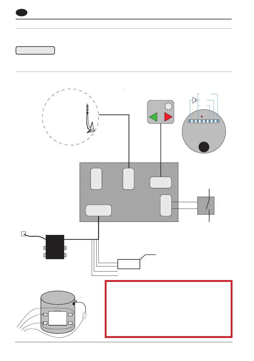
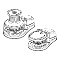
Circuit diagram for single thruster
Electric motor
3.9 Position and install the panel
3.10 Connect the electrics
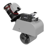
Combining a Tunnel Thruster
If combining an existing Lewmar tunnel thruster
into a dual swing/tunnel system, then the black
box must be removed from the tunnel thruster
and conversion box 58991011 installed as per
this diagram in its place. The RMC joystick must
then be used as existing Lewmar controls will
not be compatible.
Never attempt to join cables with anything other than the original plugs / sockets.
⚠ ATTENTION!
⚠
GB
O
N
L
Y
W
I
T
H
W
I
R
E
L
E
S
S
R
E
M
O
T
E
O
P
T
I
O
N
Windlass
Panel
Contactor
Battery isolator
Auto
Windlass
Panel
Motor Cable
Battery
Isolator
1. White
2. Brown
3. Green
4. Yellow
1. White
2. Brown
1. Pink
2. Grey
3. Blue
4. Red
5. Yellow
6. Brown
7. White
8. Green
Grey
Blue GND
Red 12V
Pink
Yellow
Green
Brown
White
1. Red
2. Yellow
3. Green
4. Brown
5. Pink
6. Grey
7. White
8. Blue
Yellow
White
Brow
White
Green
Connect direct to battery via 10A fuse
DO NOT connect to motor power supply
White Common plus
Brown Up/Down
Yellow Up/Down
Red +12/24V
Blue GND
Pink not in use
Grey not in use
Battery power
On/Off
STB
PRT
Heat fuse
Brow
Green
White
Yellow
White
Contactor