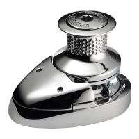
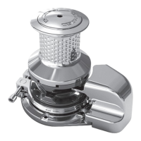
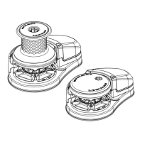
ro-Series & Pro-Fish Windlass
GB
4. Maintenanc
.1
enera
recommen
at
on
• After the fi rst two or three anchor recoveries
check the
ountin
nuts to ensure that the windlass is still fastened
ightl
to
our deck, as it should now be bedded-in.
• Regu
ar
y was
own t
e exterior of your win
ass wit
fres
a
er.
• Examine a
e
ectrica
connections for possi
e corrosion, c
ean
and lightl
grease as necessar
• Anchor rode splice should be checked regularl
and remade
if there is an
evidence of wear
• The G
ps
should be examined on a regular basis, because i
is a high wear item. The G
ps
is designed for short scopes
of c
ain an
wi
ast
onger if proper
y use
.
5. Dismantling procedures
.1 Gypsy replacement (Pro-Series
Remove t
e C
utc
Nut
1
, anti-c
oc
wise using t
e c
utc
operating
ever. Wit
raw t
e Gypsy Cone
2
, carefu
y set asi
e
t
e two Stain
ess Stee
Drive Pins
28
. Pu
t
e Contro
Arm
8
into t
e uprig
t position. Remove t
e Screws
31
t
at retain
the Stri
er (4) usin
a 4 mm (
5
32
”
Allen Wrench. Remove the
G
ps
assembl
. Remove the stripper from the G
ps
. To replace
the G
ps
, reverse the above procedure.
.2
ypsy rep
acement
Pro-F
s
Remove t
e S
ou
er Screw
45
antic
oc
wise using a 8 mm
1
A
en wrenc
. Remove t
e Was
er
46
from t
e centre
of t
e Pro-Fis
Drive Cap
36
. Loc
t
e Pro-Fis
P
unger
38
in, using t
e Stopper
41
. Remove t
e Pro-Fis
Drive
Ca
(36) anticlockwise. Remove Socket Head Ca
Screws (10)
anticlockwise, usin
a 4 mm (
Allen wrench. Remove the
Pro-Fish Stopper Cam (37). Remove the G
ps
assembl
(3)
and Stri
er (4) from the unit. Remove the Stri
er (4) from
the G
ps
(3).
To replace the G
ps
, reverse the above procedure. Clean
t
rea
of S
ou
er Screw
45
an
use Loctite® 638
66200160
Loctite® 2701 or 262 may a
so
e use
on t
rea
uring re-
assem
y. T i g
ten
o
t to 21 Nm
15.4
ft
an
a
ow at
east
15 minutes for t
e Loctite® to cure
efore use.
.3
ontro
arm rep
acemen
To remove the Control Arm (8) rotate it to the vertical
osition.
Unscrew the Grub Screw (33) usin
a 2 mm (
”
Allen Wrench
b
3 mm (
”
. Allow the Control Arm to return to its normal
position. Wit
raw t
e Contro
Arm Pivot
6
using a 4 mm
A
en wrenc
. T
e A
en wrenc
s
ou
e use
initia
y
to pus
t
e Contro
Arm Pivot in towar
s t
e center
ine of t
e
win
ass. On
oing t
is t
e Torsion Spring
7
wi
ten
to turn
t
e Contro
Arm Pivot an
A
en wrenc
c
oc
wise. A
ow it
to travel clockwise as far as it can and, usin
some side force
on the wrench
withdraw the Pivot. Remove the Control Arm
Pivot Pin Washer (34) and Torsion S
rin
from the maincase.
Reverse this
rocedure to re
lace the Control Arm. Place the
Torsion Spring in t
e
o
e, ensuring t
at t
e outer tang is a
igne
para
e
to t
e ri
ge on t
e maincase an
t
e
og
eg is para
e
to t
e
ec
. P
ace t
e Pivot Pin Was
er in
oar
of t
e fl ange
an
offer up t
e Contro
Arm suc
t
at it is pointing at t
e two
o’clock position. Pick up the Pivot Pin, align the groove on its
head also to the two o’clock
osition. Insert it throu
h the hole
on the maincase and en
a
e the s
rin
with its slot. Holdin
the Control Arm in
osition, use the Allen wrench to
ush the
Pivot Pin in. Then turn it anti-clockwise as far as it will
o. Usin
si
e force again, pu
t
e wrenc
out unti
t
e
ea
of t
e Pivot
Pin sits s
ig
t
y prou
of t
e case. Rotate t
e contro
arm to t
e
vertica
an
, app
ying a spot of Loctite® 2701 t
rea
oc
, fu
re ti
hten the Grub Screw
5.4
s
r
ve s
a
t re
acement
u
r
cat
on serv
ce
• N
TE: Lu
r
cat
on an
nterna
parts w
not
a
out w
en t
e w
n
ass
s
sassem
e
.
T
e gear train an
its
earings
ave
een
u
ricate
for you wit
SFG 100
rease an
s
ou
not re
uire re
u
ar attention. SFG is
a white s
nthetic grease containing PTFE. Use grease of a simila
s
ecifi cation throu
hout. It is recommended that the external
Drive Shaft com
onents be stri
ed, cleaned and re-
reased a
least annuall
. To do this, the G
ps
(3) and Stripper (4) should
e remove
as
etai
e
a
ove. To inspect t
e Maincase Wipe
Sea
29
for signs of wear t
e Mains
aft must
e remove
as
etai
e
e
ow. If t
e sea
is foun
to
e unservicea
e, t
e
Gypsy Drive S
aft
30
wi
ave to
e wit
rawn an
t
e sea
re
laced. Remove the Gear train Cover (17) usin
a 4 mm (
32
”)
All
n Wr
n
h
If there is sealant
resent, use a razor blade to cut throu
h it.
Withdraw the 1st Compound Gear Assembl
(16), taking care
not to
ose t
e Tefl on™ F
at Was
ers
14
. Remove t
e 2n
Compoun
Gear Assem
y
22
.
• N
TE: Rotate t
s gear assem
y as you pu
on
t, eventua
y t
s act
on w
or
entate a
at on its washer and allow the assembly
to pass the Drive Shaft Gear
25
.
Remove the External Circli
(23) and withdraw the Drive Shaf
Gear (25). Gentl
tap the Drive Roller (27) through the Drive
h
f
The Drive Shaft can now be withdrawn with or without the G
ps
Assem
y attac
e
, provi
e
t
e Stripper is no
onger attac
e
to t
e Case. Remove t
e Sea
an
rep
ace it wit
a new one.
C
ean t
e strippe
own components in
erosene,
ry t
em an
inspect t
em for wear
To reassem
e, reverse t
e a
ove proce
ure. Re
ui
t
e
windlass applying generous amounts of grease.
Isolate the windlass electrically, before carryin
out any
int
n
n
w
rk.
DO NOT use a screwdriver or shar
ed
ed tool to
ry the Gear
rain Cover o
en
 Loading...