7
ro-Series & Pro-Fish Windlass
GB
. E
ectrica
wirin
insta
atio
.1 E
ectr
c ca
e se
ect
o
To ac
ieve t
e
est performance an
to safeguar
your e
ectrica
system it is essentia
t
at any e
ectrica
win
ass
e fi tte
wit
suffi cient
y
arge
iameter ca
e to cope wit
t
e current
raw
imposed upon it and to keep the voltage drop within acceptable
limits. In an
circumstance voltage drop due entirel
to cable
r
i
n
h
l
n
x
1
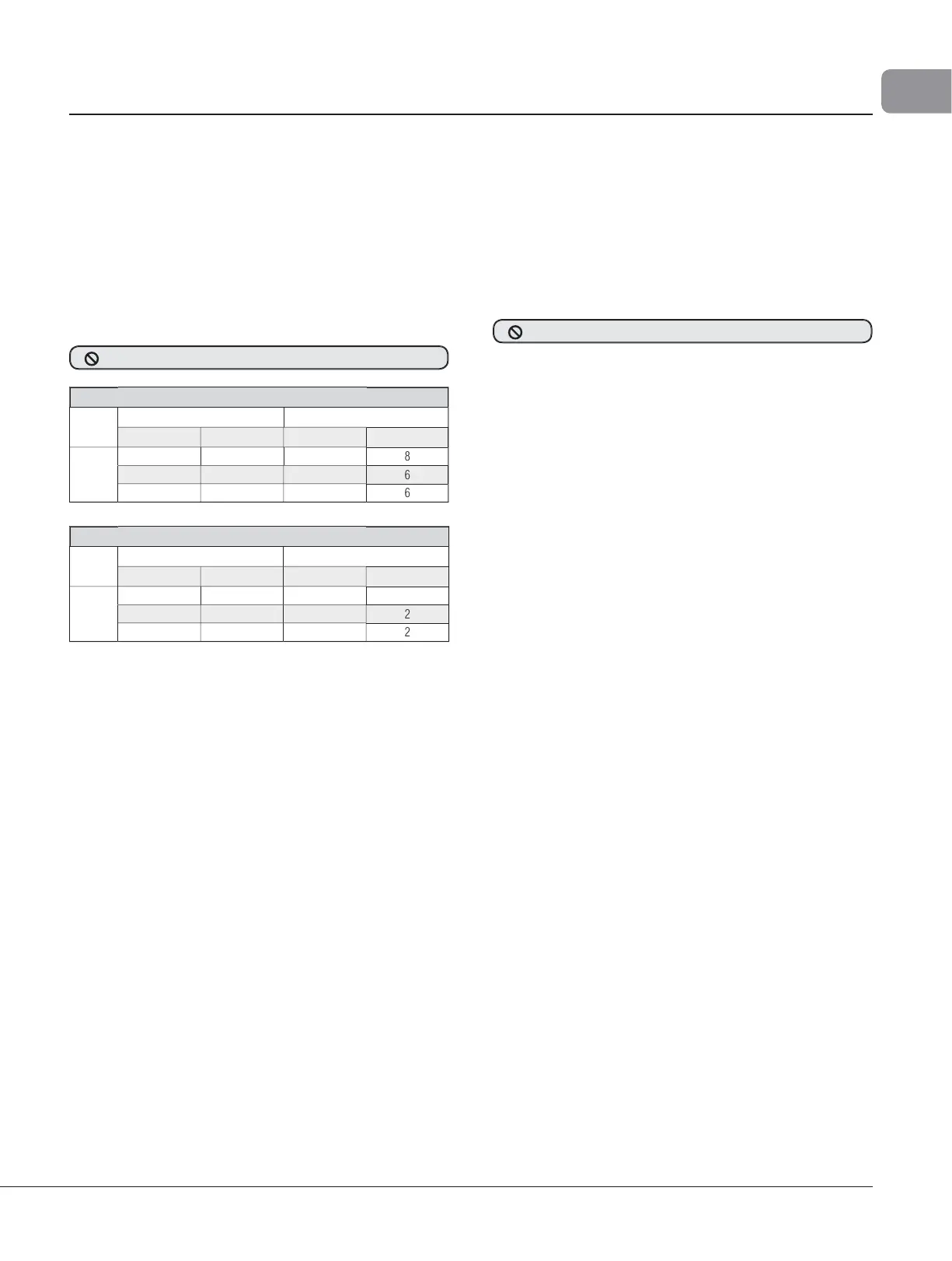
The followin
table
ives recommended cable sizes. The
recommendations are based on total len
th of cable re
uired,
from t
e
attery, fo
owing t
e route of t
e ca
es.
• Tota
engt
o
ca
e run
s
rom t
e
attery to t
e
n
ass, an
rom t
e w
n
ass
ac
to t
e
attery
Model 7
cable selection
V
lt
able Length
ize
t
AW
- 1
- 4
1
1
.
- 1
41 -
1
1
.
- 2
1 -
1
M
l 1000
l
l
ti
o
t
Cable Len
t
iz
f
W
- 1
0 - 50
6
15.5 - 2
1 - 7
1.5 -
0.
1 - 10
• In Mu
ti Station insta
ations 14 AWG wire
1.5 mm² cross
ectional area, 21/0.30 PVC covered) is used to connect the
witches to the reversin
control box.
2.2 W
r
n
P
an t
e insta
ation to suit t
e contro
s an
give t
e operator a fu
view of t
e win
ass. T
e wiring system s
ou
e of t
e two ca
e
fu
y insu
ate
return type, w
ic
avoi
s possi
e e
ectro
ytic
corrosion problems. We recommend the use of type III stranded,
tinned co
er wire with co
er crim
terminals. Most modern
installations are negative return (negative ground) but polarit
should be checked. If necessar
add a grounding strap between
the mountin
studs and an earthin
oint.
In a Mo
e
1000 insta
ation, t
e contactor must
e site
in a
ry
ocation
If a contactor is insta
e
in an anc
or
oc
er it is expose
to
ars
conditions it is not designed to withstand. Furthermore this type
of installation will void
our warrant
Overload
rotection, in the form of the circuit breaker/isolato
su
lied, must be built into the windlass wirin
circuit. This
rotects the wirin
and
revents undue dama
e to the windlass
motor, in the event of its being stalled b
an excessive load in
serv
ce
It is a
visa
e to site t
e circuit
rea
er
iso
ator in a
ry,
rea
i
y accessi
e p
ace. T
e Brea
er
Iso
ator supp
ie
mus
e manua
y reset s
ou
an over
oa
occur t
at causes it to trip
to t
e off position
• NOTE: Crim
terminals should be used on all wire
ends wherever possible for
ood electrical contacts.
If
ou are not sure
ou understand these guidelines, see
rofessional hel
2.3 Control Switch Installation
Fo
ow t
e mounting instructions supp
ie
wit
t
e switc
.
Remem
er, in a Mu
ti Station insta
ation a
switc
es must
e
wire
in a para
e
circuit
DO NOT confuse cable Len
th with the len
th of the vessel!
N
T install the contactor in the anchor locker

 Loading...