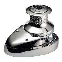
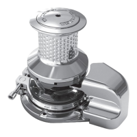
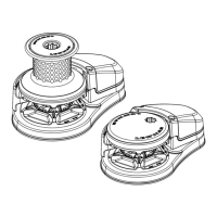
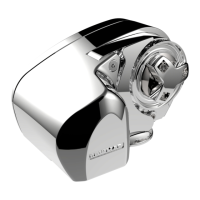
ro-Series & Pro-Fish Windlass
GB
. Insta
atio
.1 G
s
suitabilit
Gypsies fi tte
to t
e Pro-Series range of win
asses are i
ea
y
suite
to
an
ing our factory ma
e Rope
C
ain com
ination
rodes, which consist of rope spliced to a chain tail.
Ropes use
must
e win
ass gra
e, me
ium
ay ny
on. Ropes
from
ifferent manufacturers
ave wi
e variations in stretc
an
consistenc
in diameter. Therefore, rope and chain from other
manufacturers ma
require some experimentation to determine
the o
timum size.
Should
ou have diffi cult
in matching a g
ps
to
our chain
please consult
our local agent or our international network of
L
wm
r
i
ri
r
w
rl
wi
.2 Packa
e content
• Win
ass
• Inte
igent Mounting Stu
s, Was
ers an
Nuts
• A
-in-
n
In
i
n Wr
n
L
v
r
• B
k
l
• Safet
Instructions
• Mountin
Tem
late
• In
r
i
n B
kl
• Warrant
Registration Card
• Breaker
Isolator
• Control Switch (Pro-Series 700 onl
)
• Guar
e
Roc
er Switc
Pro-Series 1000 on
y
• Contactor
Pro-Series 1000 on
y
.3 Additional requirement
Eac
insta
ation requires:
Windla
in
tallation
The followin
tools:
• 10 mm
Drill.
• 75 mm
3”
Hole saw.
• An a
ro
riate marine sealant.
W
r
n
nsta
at
on
T
e fo
owing too
s:
• Crimping p
iers
wire stripper.
• Suita
e e
ectrica
ca
e an
crimp termina
s.
M
l Gy
s
hain Ro
7
C0762
mm
”
i
h Test G-4 ISO
1
mm or
stran
edium la
or
plait n
lo
7
C067
6 mm
NON USA
2 mm
NON USA
1
C085
mm (
6
igh Test G-4 ISO
4-1
mm or
1
strand medium la
o
plait n
lo
1.4 Accessorie
Use on
y Lewmar parts an
accessories to ensure top performance
an
e
iminate t
e ris
of voi
ing your warranty. For rep
acemen
parts, p
ease see t
e Parts section or visit your nearest
ea
er o
the Lewmar website
1.5 S
ecifi cation
Model 7
Maximum
ul
20 k
700 lb
Maximum line s
ee
2 m/min
105 ft/min
T
pical working load
k
175 lb
Normal line s
ee
7 m/min
t/min
oat siz
u
to 10.7 m
5 ft
Model
Maximum
ul
454 k
1000 lb
Maximum line s
ee
2 m/min
105 ft/min
12 V
T
pical working load
14 k
250 lb
Normal line s
ee
7 m/min
88 ft/min
12
o
t
iz
u
to 1
.7 m
45 ft
1.6 F
tt
ng t
e w
n
ass to t
e
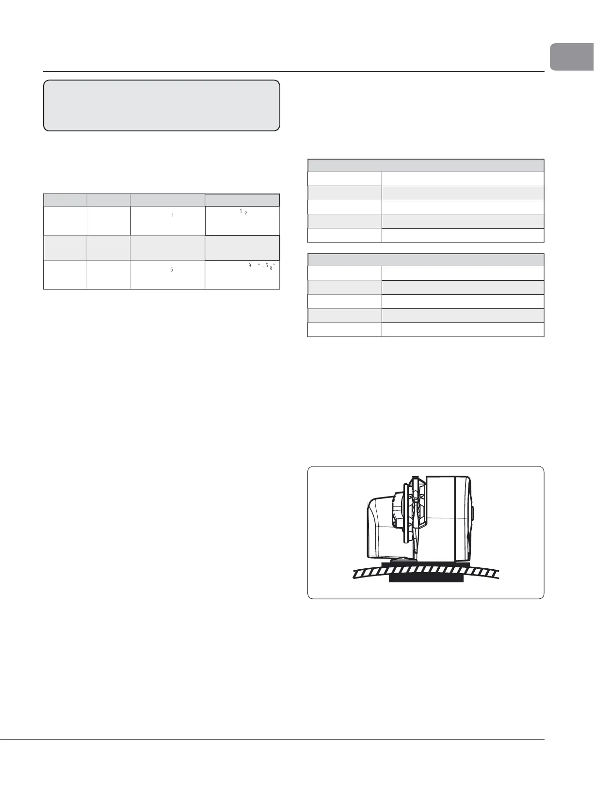
ec
• If t
e
ec
is not fl at, a suita
e mounting pa
may
e require
to ta
e up cam
er or s
eer
Dec
s t
at are t
in, or of foam or
a
sa
aminate construction,
wi
require reinforcement in or
er to sprea
t
e
oa
s t
a
will be a
lied to the deck while the windlass is in use.
The standard 8 mm
5
) threaded mountin
studs su
lied
suit deck and
ackin
thickness of u
to 76 mm (3”). These
are ade
uate for most installations.
Fi
.
.
.
• Place the windlass on the deck and decide u
on a
osition for
it with reference to the vessel’s bow roller (Fi
. 1.6.2) and the
chain locker below. Rode lead from the roller should ideall
be fed horizontall
back to the top of the g
ps
and along its
center
ine
Fig. 1.6.3
.
T
ere must
e suffi cient vertica
fa
for t
e c
ain or rope,
even wit
a fu
oc
er, to
raw t
e ro
e from t
e gypsy w
en
au
ing in
• Pro-
eries & Pro-Fish Manual
All references re
ardin
installation and wirin
tc. of Pro-Series a
l
to the e
uivalent
ro-Fish model
700 or 1000
 Loading...