EasyManuals Logo

Lewmar V1 Owners Installation, Operation & Basic Servicing Manual

Lewmar V1
9 pages
To Next Page IconTo Next Page
To Previous Page IconTo Previous Page
Page #4 background imageLoading...
Page #4 background image
6
V
1 Windlas
s
7
V
1
Windlass
GB
DO NOT use a
p
ermanent adhesive/sealant, e.
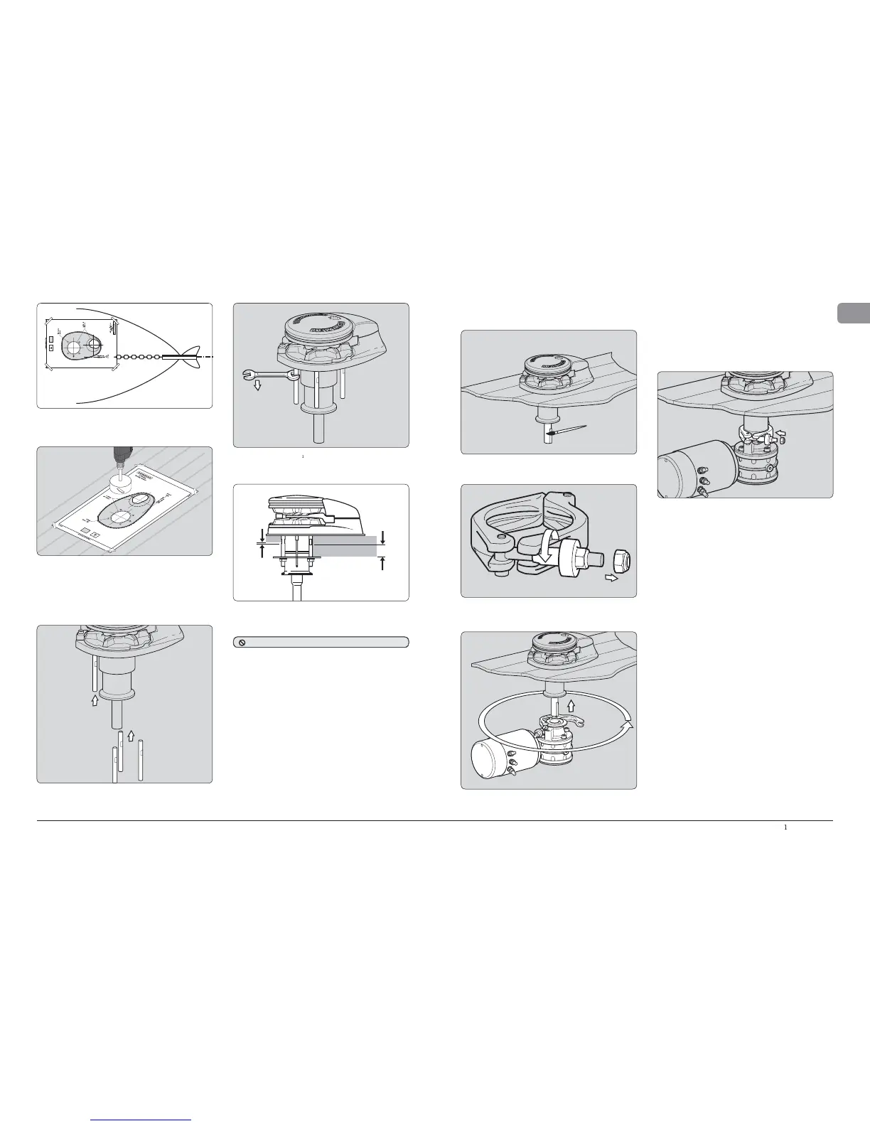
g
., 520
0
• Usin
g
a 10 mm
(
3
/
8
”)
diameter drill, make the ve holes fo
r
t
h
e mountin
g
stu
d
s an
d
sensor. Wit
h
a 75 mm
(
3”
)
d
iamete
r
h
o
l
e saw, ma
k
e two
h
o
l
es for t
h
e ro
d
e an
d
d
own tu
b
e to pass
t
h
roug
h
.
W
h
en a
ll
t
h
e
h
o
l
es
h
ave
b
een ma
d
e, remove t
h
e temp
l
ate. To
h
e
l
p avoi
d
water a
b
sorption
b
y t
h
e
d
ec
k
, app
l
y an appropriate
marine sea
l
ant to t
h
e fres
hl
y cut
h
o
l
e e
d
ges.
W
in
dlass
Outl
in
e
Fig. 1.6-4
F
-4
• Place the mountin
g
tem
p
late on the deck or mountin
g
p
ad
in the desired
p
osition for the windlass and hold it in
p
lace
usin
g
adhesive ta
p
e
.
Fi
g
. 1.6-
5
• Fu
ll
y screw t
h
e four mounting stu
d
s into t
h
e
b
ase of t
h
e
win
dl
ass. Screw t
h
e stu
d
s into t
h
e
b
ase fi nger tig
h
t, wit
h
t
h
e fl ats towar
d
s t
h
e
b
ase as s
h
own
(
Fig 1.6-5
)
.
Next, using a 7 mm
(
1
/
4
”)
spanner on t
h
e fl ats, tig
h
ten t
h
e
s
tu
d
s unti
l
t
h
ey
b
ottom out in t
h
eir
h
o
l
es. Do t
h
is to eac
h
of
th
e stu
d
s in turn
.
F
i
g
. 1.6-
6
As a ru
l
e of t
h
um
b
, if t
h
e fl ats on t
h
e stu
d
s are visi
bl
e
b
e
l
ow
d
ec
k
, t
h
e
d
ec
k
an
d/
or any pac
k
ing is
l
i
k
e
l
y to
b
e too t
h
in to
o
ffer a
d
equate support w
h
en t
h
e win
dl
ass is un
d
er
l
oa
d
.
N
O
TE: I
f
us
i
ng s
ili
cone or ot
h
er ru
bb
ery type
s
ealant, it is advisable to allow curin
g
of the sealan
t
b
efore fi nal ti
g
htenin
g
of the mountin
g
nuts
.
Fi
g
. 1.6-3
Place the base mat in position on the deck, optionall
y
, appl
y
a
suita
bl
e sea
l
ant to t
h
e
b
ase of t
h
e win
dl
ass, any mounting
p
a
d
or aroun
d
t
h
e stu
d
s
.
F
ig.
1
.
6
-
7
Windlass
Outline
1.7 F
i
tt
i
ng t
h
e motor gear
b
o
x
Un
d
er t
h
e
d
ec
k
l
ig
h
t
l
y coat t
h
e s
h
aft wit
h
grease
b
efore
a
ssem
bl
ing t
h
e motor gear
b
ox.
Remove the n
y
loc nut from the end of the Fast Fit clamp bolt
a
n
d
screw t
h
e
b
ronze nut up to t
h
e en
d
of t
h
e t
h
rea
d.
F
i
g
. 1.7-
1
O
p
en u
p
the Fast Fit clam
p
and offer the
g
earbox u
p
to the
a
bove deck unit, slidin
g
the shaft into the
g
earbox. Ensure
t
he drive ke
y
is in place.
F
i
g
. 1.7-2
Fig. 1.7-
3
F
ig. 1.7-
4
• P
l
ace t
h
e gear
b
ox up t
h
e s
h
aft an
d
rotate it into a suita
bl
e
p
osition before finall
y
pushing home onto the location
do
w
e
l
s.
Swin
g
the Fast Fit clam
p
shut and ti
g
hten u
p
the bronze
nut b
y
hand. If required
y
ou can remove the plastic location
p
lu
g
holdin
g
the Fast Fit clam
p
in
p
lace and rotate the
c
l
amp aroun
d
t
h
e gear
b
ox fl ange to give a
b
etter
l
ocation
f
or tig
h
tening up t
h
e nut
.
• Ti
g
hten u
p
the bronze nut to 15 Nm (11 lb/ft) before addin
g
t
h
e Ny
l
oc nut. Tig
h
ten t
h
e Ny
l
oc nut up
b
e
h
in
d
t
h
e
b
ronze
nu
t
.

Other manuals for Lewmar V1

Questions and Answers:

Question and Answer IconNeed help?

Do you have a question about the Lewmar V1 and is the answer not in the manual?

Lewmar V1 Specifications

General IconGeneral
BrandLewmar
ModelV1
CategoryMarine Equipment
LanguageEnglish

Related product manuals