EasyManuals Logo

Lewmar V1 Owners Installation, Operation & Basic Servicing Manual

Lewmar V1
9 pages
To Next Page IconTo Next Page
To Previous Page IconTo Previous Page
Page #5 background imageLoading...
Page #5 background image
8
V
1 Windlas
s
9
V
1
Windlass
GB
Ch
oice of ca
bl
e t
h
ic
k
ness
d
epen
d
s on tota
l
ca
bl
e
l
engt
h
:
A
+ B + C + D + E =
B
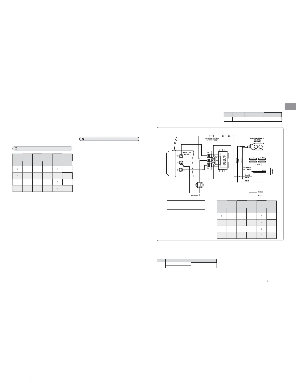
attery to windlass, windlass to batter y
.
CIRCUIT BREAKER
12V - 68000349 - 90A
GUARDED
ROCKER
SWI T CH
(68000593)
Thermal
Cut-out
Thermal
Cut-out
ELECTRIC SWITCH KIT
(UP - 69000352) (DOWN - 69000353)
Fig.
2
.4-1
2.4 V1 W
i
r
i
ng
di
agram
M
ode
l
Mo
t
o
r Breaker
/
Isolator Contactor
V1
1
2
V
90 A (68000349
)
N/A
2. E
l
ectrica
l
wirin
g
insta
ll
ation
2.1 E
l
ectr
i
c ca
bl
e se
l
ect
i
on
To ac
h
ieve t
h
e
b
est performance an
d
to safeguar
d
your e
l
ectrica
l
system it is essentia
l
t
h
at any e
l
ectrica
l
win
dl
ass
b
e fi tte
d
wit
h
suffi cient
l
y
l
arge
d
iameter ca
bl
e to cope wit
h
t
h
e current
d
ra
w
imposed upon it and to keep the voltage drop within acceptable
limits. In an
y
circumstance voltage drop due entirel
y
to cable
r
es
i
sta
n
ce
s
h
ou
l
d
n
ot
e
x
ceed
1
0%.
The followin
g
table
g
ives recommended cable sizes. The
recommendations are based on total len
g
th of cable re
q
uired,
from t
h
e
b
atter
y
, fo
ll
owing t
h
e route of t
h
e ca
bl
es.
• Tota
l
l
engt
h
o
f
ca
bl
e run
i
s
f
rom t
h
e
b
attery to t
h
e
w
i
n
dl
ass, an
d
f
rom t
h
e w
i
n
dl
ass
b
ac
k
to t
h
e
b
attery.
• In Mu
l
ti Station insta
ll
ations 14 AWG wire
(
1.5 mm² cross
sectiona
l
area, 21
/
0.30 PVC covere
d)
is use
d
to connect t
h
e
switc
h
es to t
h
e reversing contro
l
b
ox.
2
.2 W
i
r
i
ng
Pl
an t
h
e insta
ll
ation to suit t
h
e contro
l
s an
d
give t
h
e operator a fu
ll
v
iew of t
h
e win
dl
ass. T
h
e wiring system s
h
ou
ld
b
e of t
h
e two ca
bl
e
f
u
ll
y insu
l
ate
d
return type, w
h
ic
h
avoi
d
s possi
bl
e e
l
ectro
l
ytic
c
orrosion problems. We recommend the use of Type III stranded,
t
inned co
pp
er wire with co
pp
er crim
p
terminals. Most modern
i
nstallations are negative return (negative ground) but polarit
y
s
hould be checked. If necessar
y
add a grounding strap between
t
he mountin
g
studs and an earthin
g
p
oint.
I
f a contactor is insta
ll
e
d
in an anc
h
or
l
oc
k
er it is expose
d
to
h
ars
h
c
on
d
itions it is not
d
esigne
d
to wit
h
stan
d
. Furt
h
ermore t
h
is type
o
f insta
ll
ation wi
ll
voi
d
your warranty.
O
ver
l
oa
d
protection, in t
h
e form of t
h
e circuit
b
rea
k
er
/
iso
l
ator
s
upplied, must be built into the windlass wiring circuit. This
p
rotects the wirin
g
and
p
revents undue dama
g
e to the windlass
m
otor, in the event of its being stalled b
y
an excessive load in
se
rvi
ce.
I
t is advisable to site the circuit breaker/isolator in a dr
y
,
r
ea
d
i
l
y accessi
bl
e p
l
ace. T
h
e Brea
k
er
/
Iso
l
ator supp
l
ie
d
must
b
e manua
ll
y reset s
h
ou
ld
an over
l
oa
d
occur t
h
at causes it to trip
t
o t
h
e off position.
N
O
TE: Pr
i
or to
tt
i
ng cr
i
mps on t
h
e motor en
d
o
f
t
he cables fi t a rubber boot supplied, to the end o
f
e
ach cable. Apply a layer of
g
rease to the inside o
f
t
he rubber boot to further
p
rotect the connection.
NOTE: Crim
p
terminals should be used on all wire
e
nds wherever possible for
g
ood electrical contacts.
I
f
y
ou are not sure
y
ou understand these guidelines, seek
p
rofessiona
l
h
e
l
p. Ensure t
h
at t
h
e insta
ll
ation comp
l
ies wit
h
U
SCG, ABYC, NMMA or ot
h
er
l
oca
l
regu
l
ations.
2
.3 Control
s
witch in
s
tallation
F
o
ll
ow t
h
e mountin
g
instructions su
ppl
ie
d
wit
h
t
h
e switc
h
.
R
emember
,
in a multi station installation all switches must be
w
ired in a
p
arallel circuit.
D
O NOT confuse cable Len
g
th with the len
g
th of the vessel
!
D
O
N
O
T install the contactor in the anchor locker.
Boat
L
en
g
t
h
Cable Len
g
th
Up
T
o
Cable Siz
e
m
(
ft
)
(
ft
)
(
m
)
(
AWG
)
(
mm
2
)
7
25
0 -
33
0
- 1
0
6
1
6
9
30
3
4 - 60
1
1 - 1
8
3
2
5
1
1
35
6
1 -
80
19
-
2
4
2
3
5
1
4
4
5
8
1 - 1
25
25
- 3
8
0
50
Boa
t
L
en
g
t
h
Cable Length
Up
T
o
C
able
S
iz
e
m
(
ft
)
(
ft
)
(
m
)
(
AWG
)
(
m
m
2
)
7
25
0
- 3
3
0 - 1
0
6
16
9
30
3
4 - 60 11 - 1
8
3
2
5
11
3
5
6
1 -
80
1
9
-
24
2
35
14 45
8
1 - 1
2
5
2
5 -
38
0
5
0
N
O
TE: W
i
re
l
ess remote a
l
so ava
il
a
bl
e.
Model
I
t
em
D
escr
i
pt
i
o
n
Wi
re
l
e
ss
R
emote
s
680008
4
4
3
Button Windlass onl
y
680008
4
5
5 Button Windlass
&
Thruster
N
O
TE: W
i
re
l
ess remote can on
l
y
b
e use
d
i
f a contactor is fi tted.
S
ee wireless remote
i
nstructions for wirin
g
details
.
Th
e sma
ll
re
d
an
d
bl
ac
k
s
l
eeve
d
w
i
res on t
h
e
W
indlass unit are sensor wires to a chain
cou
nt
e
r if fi tt
ed
.

Other manuals for Lewmar V1

Questions and Answers:

Question and Answer IconNeed help?

Do you have a question about the Lewmar V1 and is the answer not in the manual?

Lewmar V1 Specifications

General IconGeneral
BrandLewmar
ModelV1
CategoryMarine Equipment
LanguageEnglish

Related product manuals