Do you have a question about the Lex System 2I392CW and is the answer not in the manual?
Lists key hardware specifications and capabilities of the 21392CW motherboard.
Provides detailed technical specifications including SOC, memory, graphics, I/O, and dimensions.
Step-by-step guide with images on how to install the SO-DIMM memory module.
Instructions and visuals for safely removing the SO-DIMM memory module from the motherboard.
Detailed steps and images for installing a full-size Mini PCI-e card into the motherboard.
Lists all items included in the product package with their material codes and descriptions.
Details essential precautions to take before unpacking and handling the motherboard.
Steps to verify the contents of the delivery package and check for any damage or missing components.
Provides detailed physical dimensions of the 21392CW motherboard with diagrams.
Diagram showing the layout of connectors and jumpers on the top side of the 21392CW motherboard.
Diagram illustrating the layout of connectors and jumpers on the bottom side of the 21392CW motherboard.
Diagram mapping various functions to specific connectors and components on the top side.
Diagram mapping various functions to specific connectors and components on the bottom side.
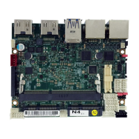
A clear diagram of the motherboard's top side, labeling key components and connectors.
A clear diagram of the motherboard's bottom side, labeling key components and connectors.
Maps connector functions on both top and bottom views of the motherboard.
Lists the available jumpers on the motherboard and their primary functions.
Explains how jumpers are set to ON or OFF states and how to use them.
Details how to use the JSB1 jumper to clear CMOS settings for troubleshooting.
Explains the JVL1 jumper for selecting the LCD panel power voltage (+5V or +3.3V).
Describes the JVC1/JVC2 jumpers for COM port RI and power selection.
Provides a comprehensive list of all connectors on the motherboard.
Details the CBT1 connector for the 3V CMOS battery, including pinout and notes.
Describes the CA3 (Line-out/Line-in/Mic-in) and CALR1 (Amplifier) audio connectors and their pinouts.
Details the CC1/CC2 connectors for COM ports, supporting RS232, RS485, and RS422 modes.
Explains the CFP1 connector for front panel controls like power buttons and LEDs, including its pinout.
Covers the CIO1 connector for digital I/O and information on the F75111 Watch Dog Timer.
Instructions for using the F75111 IO device demo application under DOS, including download and usage.
Information on the F75111 IO device demo tool for Windows, focusing on DIO and WDT functionality.
Details the F75111 IO device demo application for VB6 on Windows, with screenshots and function descriptions.
Guide to compiling and using the F75111 IO device demo application under Linux.
Describes the RJ45 LAN ports (CL1/CL2, CL11/CL21) and their LED status indicators.
Details the CO1 connector for the I²C bus interface, including pinout.
Explains the CPI1 connector for DC power input, specifying voltage requirements.
Describes the CPO1 connector for +12V/+5V DC voltage output, including pinout.
Details the CU12 (Dual-USB3.0/2.0) and CU3/CU4 (USB3.0/2.0) Type A connectors and their pinouts.
Describes HDMI connectors (Type A) and optional DP connectors, including pinouts.
Details the CPP1 connector for panel inverter power, including PWM dimming control.
Explains the CT1 connector for touch screen input, detailing pinouts for 8-wire, 4-wire, and 5-wire types.
Describes the SATA1 port connector, its pinout, and specifications.
Details the LEX eIO connector, listing all pins and their functions for expansion.
Describes the MPCE1/MPCE2 full-size mini card slots and their supported interfaces (USB, PCIe, mSATA).
A comprehensive list of motherboard connectors, their brands, mating connectors, and cable housings.
Instructions on how to access the BIOS setup utility upon system startup.
Overview of the BIOS setup utility interface, key functions, and menu bar options.
Explains how to access help within the BIOS setup utility and describes navigation keys.
Describes the main BIOS menu screen, system information display, and how to modify settings.
Introduces the 'Advanced' section of the BIOS setup, detailing sub-sections.
Details options for configuring video settings, including aperture size and DVMT pre-allocation.
Outlines the sub-menu for South Cluster configuration, including HD-Audio, PCI Express, and SATA drives.
Explains how to enable or disable the HD-Audio support within the BIOS.
Details options for configuring PCI Express root ports, including EIO P1 and MPC1/EIO P2.
Covers settings for MPC1/EIO P2, including PCIe speed and the MPCE/EIO switch.
Describes how to configure SATA drives, including chipset SATA controller, mode, and interface speed.
Explains thermal configuration parameters, including critical and passive trip points for system shutdown.
Details the configuration of Serial Ports A/B, Base IO Address, Interrupt, and Serial Mode.
Covers setting up supervisor passwords for system security.
Details options for Wake On LAN and ACPI S3 sleep state support.
Covers boot type, quiet boot, network stack, PXE, and EFI settings.
Explains options for saving changes, exiting, loading defaults, or discarding changes.
Step-by-step guide for installing the Intel Apollo Lake Chipset Driver using the provided setup utility.
Instructions for installing the Intel Apollo Lake VGA Driver, including license agreement and setup steps.
Guide to installing the Intel Apollo Lake Serial IO Driver, covering license, setup type, and completion.
Steps for installing the Realtek High Definition Audio Driver, including restart prompts.
Instructions for installing the Intel LAN Driver, covering license agreement, setup options, and completion.
Guide to installing the Intel TXE Driver, including license agreement and confirmation steps.
Step-by-step instructions for updating the Insyde BIOS using a bootable disk under DOS mode.
| Memory | Up to 8GB DDR3L |
|---|---|
| Expansion Slots | 1 x Mini PCIe |
| Storage | 1 * SATA 3.0, 1 * mSATA |
| Ethernet | 2 x Gigabit Ethernet |
| USB | 4 x USB 3.0 |
| Display Output | 1 x HDMI |
| Audio | Line-out, Mic-in |
| Serial Ports | 2 x RS-232/422/485 |
| Power Input | 12V DC |
| Form Factor | 3.5" SBC |
| Chipset | Integrated in CPU |