45D0028 15
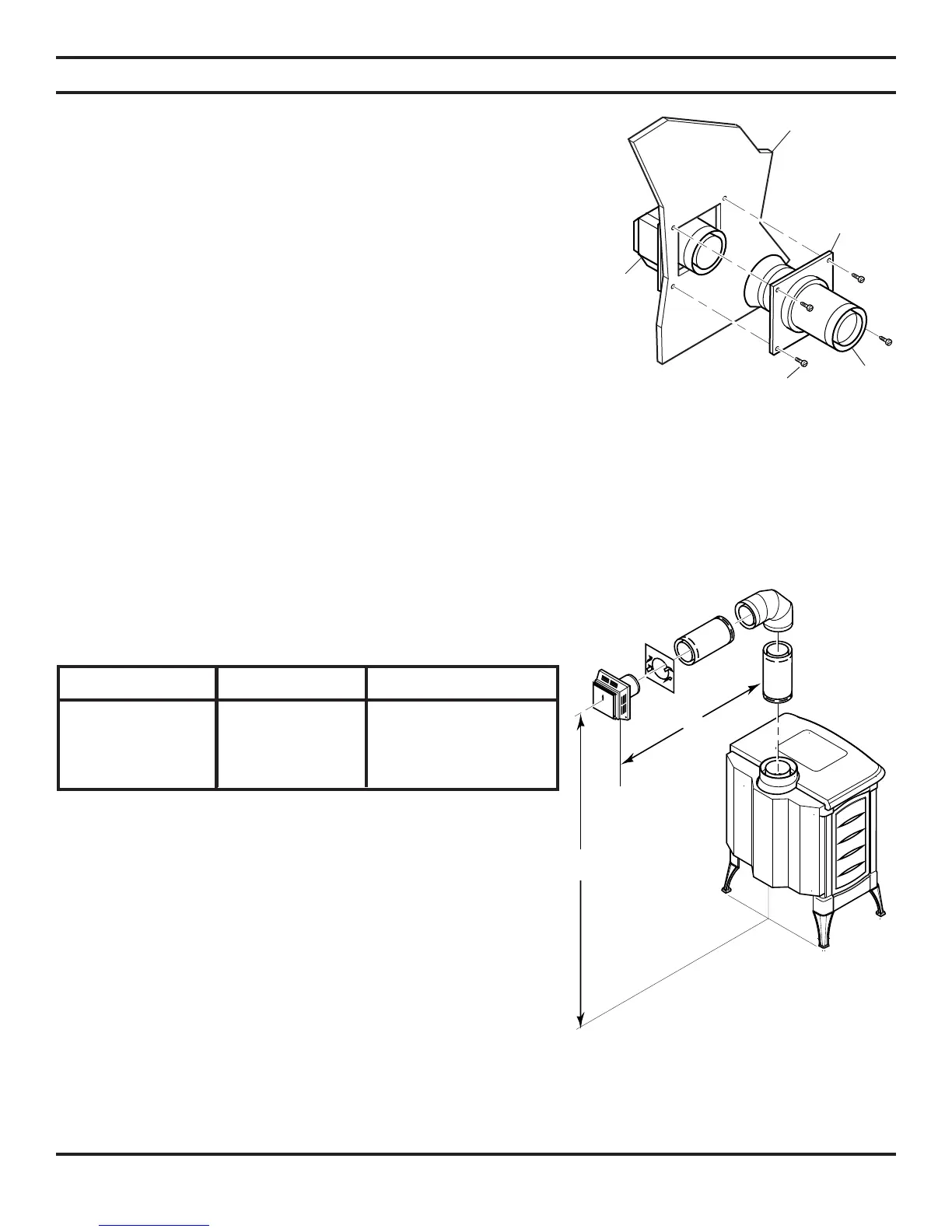
5. Slide the wall thimble over the vent pipe before connecting
the horizontal run to the vent cap. See Figure 14.
6. Carefully move the stove with vent assembly attached toward
the wall and insert the vent pipe into the horizontal termina-
tion. The pipe overlap should be a minimum of 1
1
/4" (mm).
Apply silicone to the outer pipe connection. Fasten all vent
connections with screws provided.
7. Slide the wall thimble against the interior wall surface and
attach with srews. See Figure 14.
Figure 14 - Connecting Vent Cap with
Horizontal Vent Pipe
VENT INSTALLATION
HORIZONTAL VENT INSTALLATION (CONTINUED)
Interior Wall
Surface
Decorative
Wall
Thimble
Horizontal
Vent Pipe
Screw
Vent Cap
(Horizontal
Termination)
HORIZONTAL TERMINATION CONFIGURATIONS
Figures 15 through 17 show different congurations for venting with horizontal termination. Each gure includes a chart
with vertical minimum/maximum and horizontal maximum dimensions which must be met. All horizontal terminations
require a
1
/4" rise per 12" of horizontal run.
NOTE: Add
1
/4" rise per 12" horizontal length of pipe.
Vertical C28 (V) Vertical C40 (V) Horizontal (H)
47
1
/2" minimum N/A 23" maximum (C28 only)
59
1
/2" minimum 63" minimum 31" maximum
70" minimum 73
1
/2" minimum 8' maximum
94" minimum 99" minimum 20' maximum
Table 2 - Horizontal Venting
Figure 15 - Horizontal Termination
Configuration for Rigid Venting Using
One 90° Elbow
NOTE: This configuration is for use with corner
installation also.