45D0028 19
VENT INSTALLATION
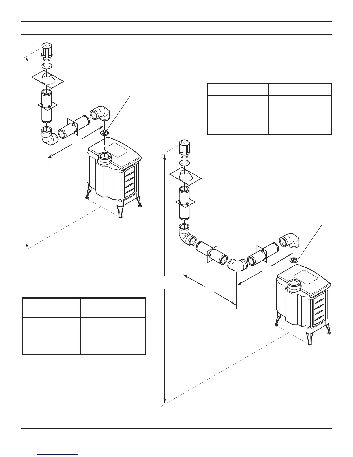
VERTICAL TERMINATION CONFIGURATIONS
Figures 23 through 26 on pages 19 and 20 show four different congurations for vertical termination.
IMPORTANT: You must install a restrictor on all vertical installations.
Figure 23 - Vertical Rigid Venting
Configuration Using Two 90° Elbows
Horizontal (H)
Vertical (V) + Horizontal (H1)
8' minimum 2' maximum
9' minimum 4' maximum
10' minimum 6' maximum
11' minimum 8' maximum
23' maximum 8' maximum
Figure 24 - Vertical Rigid Venting Configuration Using Three
90° Elbows with Two Horizontal Runs
Vertical (V) Horizontal (H)
8' minimum 2' maximum
9' minimum 4' maximum
10' minimum 6' maximum
11' minimum 8' maximum
23' maximum 8' maximum
NOTE: Install restrictor into 4" collar of
stove or first vent section as shown.
NOTE: Install restrictor into 4"
collar of stove or first vent secton
as shown.
Table 5 - Venting with Two 90° Elbows
Table 6 - Venting with Three 90° Elbows