20 45D0028
VENT INSTALLATION
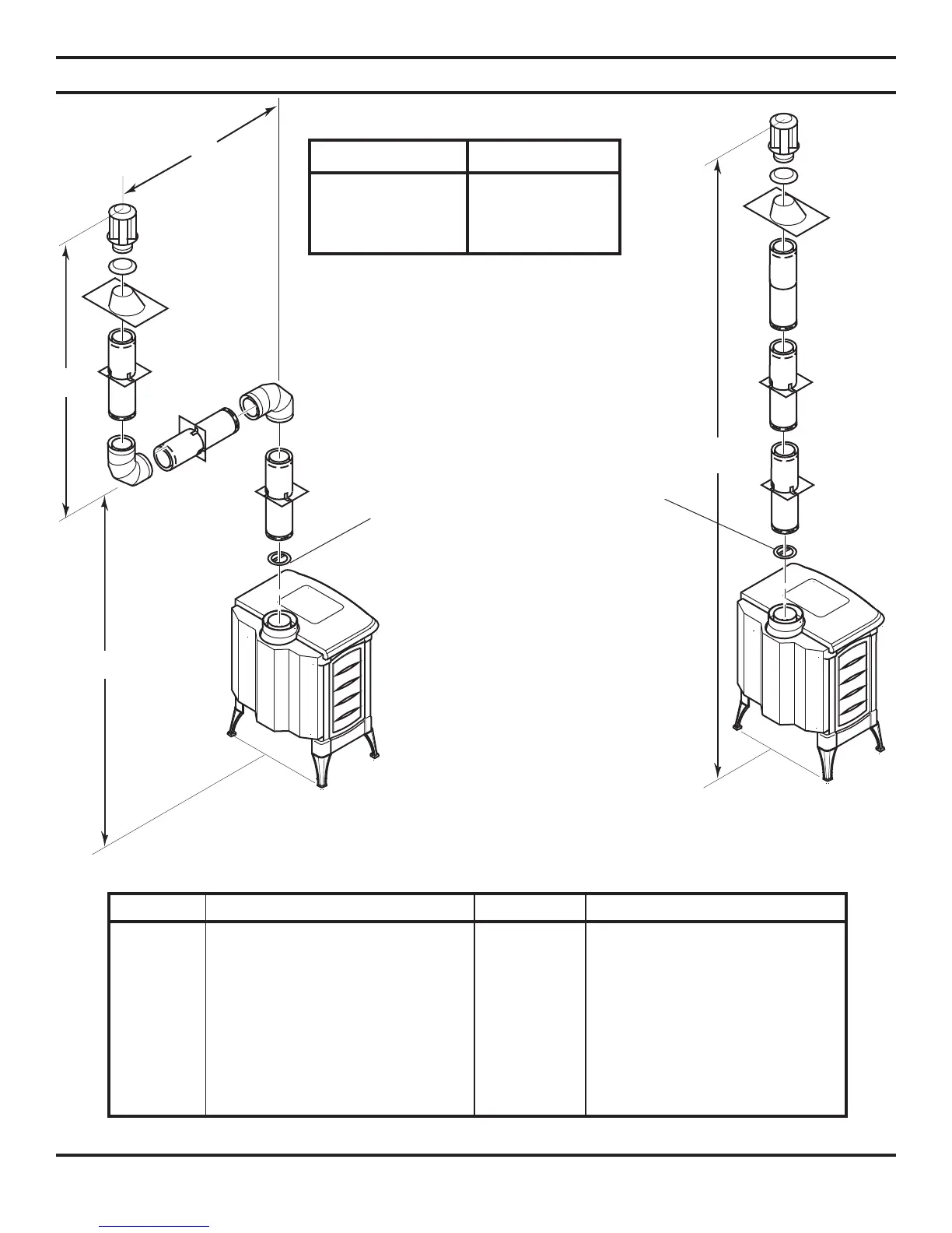
Figure 26 - Vertical Rigid
Venting Configuration
with No Horizontal run
Vertical (V+V1) Horizontal (H)
8' minimum 6' maximum
9' minimum 12' maximum
10' minimum 18' maximum
11' minimum 20' maximum
Vertical Venting
V = 40' maximum
Figure 25 - Vertical Rigid Venting
Configuration Using Two 90° Elbows
NOTE:
Vertical (V1) + Vertical (V2) = 20' Maximum
NOTE: Install restrictor into 4"
collar of stove or front vent section
as shown.
NUMBER DESCRIPTION NUMBER DESCRIPTION
902B 7" x 48" Pipe 943S Roof Flashing 7/12-12/12
903B 7" x 36" Pipe 945B 7" x 45° Elbow
904B 7" x 24" Pipe 950 Vinyl siding Standoff
906B 7" x 12" Pipe 953 Storm Collar
907B 7" x 9" Pipe 963 Ceiling Firestop
908B 7" x 6" Pipe 981 36" Snorkel Termination
911B 7" Adjustable (11" - 14
5
/8" Pipe) 984 Horizontal Termination Vent Cap
940 Wall Thimble 988 Wall Strap
941 Cathedral Ceiling Support Box 990B 7" x 90° Elbow
943 Roof Flashing 0/12-6/12 991 Vertical High Wind Termination
SIMPSON DURA-VENT GS 4" X 6
5
/8" (BLACK PIPE)
Table 7 - Venting with Two 90° Elbows
Table 8