22 58D6056
H
V
H
1
H
V
VENT INSTALLATION
VERTICAL TERMINATION CONFIGURATIONS
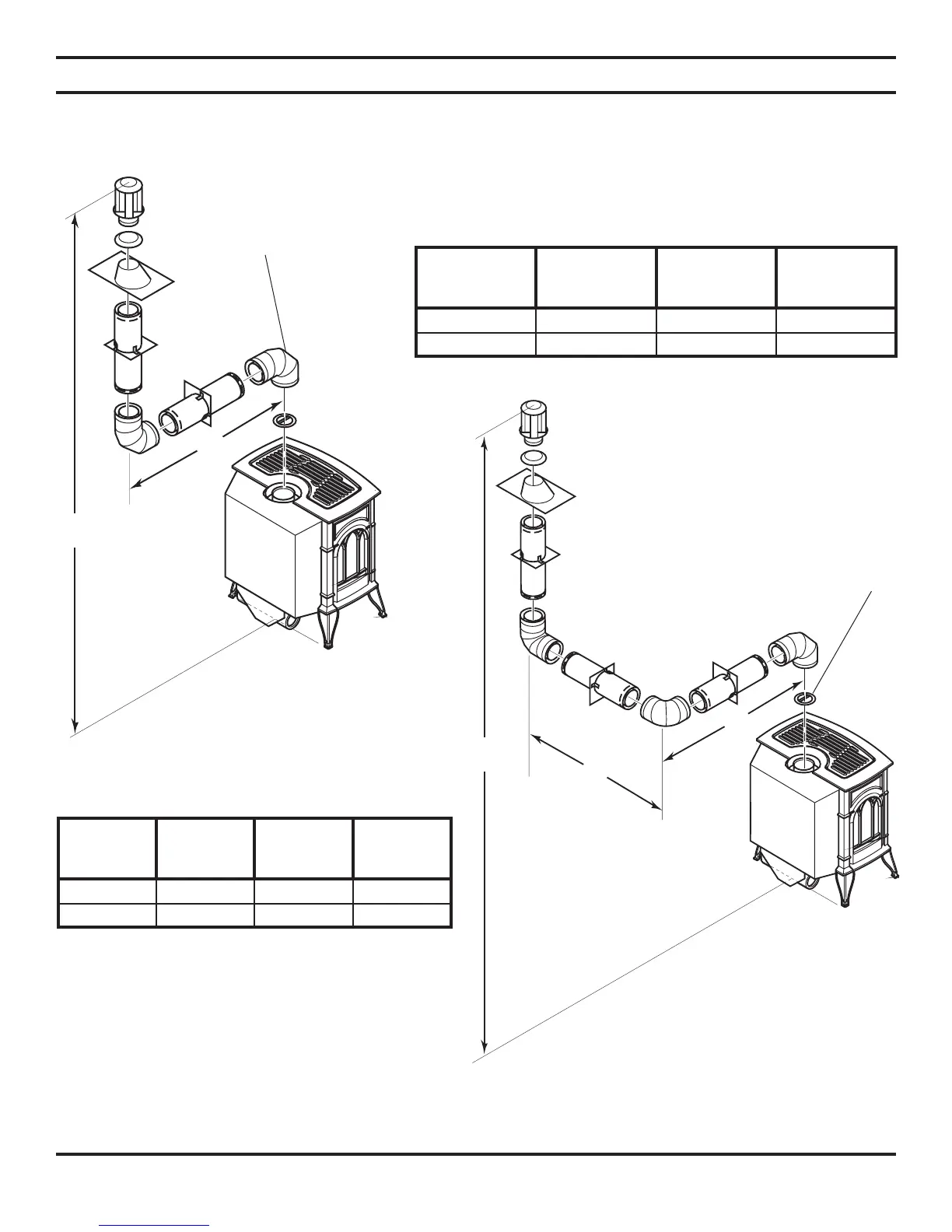
Figures 27 through 30 on pages 22 and 23 show four different configurations for vertical termination.
IMPORTANT: Install restrictor as indicated on chart (Figure 11) on page 15.
Figure 27 - Vertical Rigid Venting
Confi guration Using Two 90° Elbows
Figure 28 - Vertical Rigid Venting Confi guration Using Three
90° Elbows with Two Horizontal Runs
NOTE: Install restrictor into
4" collar of stove or fi rst vent
section as shown.
NOTE: Install restrictor into 4"
collar of stove or fi rst vent secton
as shown.
Table 5 - Venting with Two 90° Elbows
Table 6 - Venting with Three 90° Elbows
Maximum
Horizontal (H)
Vertical
Minimum
CSDV20 (V)
Vertical
Minimum
CSDV30 (V)
Vertical
Minimum
CSDV40 (V)
2' 41.50" 52.50" 54.50"
20' 95.25" 98.75" 102.25"
Maximum
Horizontal
(H)
Vertical
Minimum
CSDV20 (V)
Vertical
Minimum
CSDV30 (V)
Vertical
Minimum
CSDV40 (V)
2' 41.50" 52.50" 54.50"
20' 95.25" 98.75" 102.25"