EasyManua.ls Logo

Lexmark C4150 - User Manual

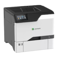
Lexmark C4150
493 pages
To Next Page IconTo Next Page
Loading...
CS720, CS725, and C4150
5028-135, -630, -639
Service Manual
Start diagnostics
Maintenance
Safety and notices
Trademarks
Index
January 25, 2016 www.lexmark.com
P/N 12G3399

Table of Contents

Questions and Answers:

Lexmark C4150 Specifications

General IconGeneral
Drivers includedYes
Print technologyLaser
Maximum resolution1200 x 1200 DPI
Time to first page (black, normal)5 s
Time to first page (color, normal)5.5 s
Print speed (black, normal quality, A4/US Letter)50 ppm
Maximum duty cycle150000 pages per month
Recommended duty cycle2000 - 20000 pages per month
Number of print cartridges1
Total input capacity550 sheets
Total output capacity300 sheets
Multi-Purpose tray input capacity100 sheets
Envelopes sizes7 3/4, 9, 10, B5, C6, DL
Paper tray media typesPlain paper, Recycled paper, Thin paper
Non-ISO print media sizesExecutive (184 x 267mm), Folio (media size), Letter (media size), Oficio (media size), Statement (140 x 216mm), Universal, Legal (media size)
ISO A-series sizes (A0...A9)A4, A5, A6
Maximum ISO A-series paper sizeA4
Wi-Fi-
Standard interfacesEthernet, USB 2.0
USB 2.0 ports quantity3
Maximum internal memory3072 MB
Sound pressure level (printing)53 dB
Control typeTouch
Product colorBlack, White
Display diagonal4.3 \
Power consumption (printing)- W
Operating altitude0 - 2896 m
Operating temperature (T-T)10 - 32 °C
Operating relative humidity (H-H)15 - 80 %
Weight and Dimensions IconWeight and Dimensions
Depth497.84 mm
Width474.98 mm
Height416.56 mm

Summary

Preface

General caution statements

Lists essential safety precautions to prevent injury or damage.

General information

Paper and specialty media guide

Guidelines for selecting, storing, and using various paper types and specialty media.

Diagnostic information

Troubleshooting overview

Provides an overview of the troubleshooting process and initial checks.

Fixing print quality issues

Details troubleshooting steps for common print quality problems.

Paper jams

Covers procedures for avoiding and clearing paper jams.

Service menus

Diagnostics menu

Details how to access and use the diagnostic menus for testing and adjustments.

Repair information

Removal precautions

Outlines essential safety precautions before performing hardware removals.

Data security notice

Provides information on identifying and erasing printer memory.

Controller board;control panel replacement

Adjustments

Printhead alignment adjustment

Procedure to correct crooked or skewed print by adjusting printhead alignment.

Registration adjustment

Process to correct image misalignment relative to paper edges after component replacement.

Removal procedures

Cover removals

General tips and specific procedures for removing printer covers.

Front cover removal

Step-by-step instructions for removing the printer's front cover.

Control panel removals

Upper control panel removal

Procedure for removing the upper section of the printer's control panel.

Duplex removals

Left removals

Motor (EP drive) removal

Detailed steps for removing the EP drive motors.

Motor (output) removal

Motor (deskew) removal

EP gear box removal

LVPS removal

Motor (black only retract) removal

Right removals

Sensor (paper size) removal

Motor (duplex;MPF) removal

Motor (fuser) removal

HVPS removal

Sensor (TPS) removal

Toner cartridge contacts removal

Front removals

Fuser removal

Step-by-step instructions for removing the printer's fuser unit.

Transfer module removal

Sensor (input) removal

Rear removals

Controller board shield removal

Procedure for removing the shield covering the controller board.

Controller board removal

Top removals

Printhead removal

Steps for removing and installing the printer's printhead assembly.

Bottom removals

Isolation unit removal

Media feeder removal

550-sheet tray removals

Motor (550-sheet tray pass-through) removal

550-sheet tray paper feeder removal

550-sheet tray controller board assembly removal

Component locations

Controller board connectors

Details connectors and pin assignments on the controller board.

Maintenance

Inspection guide

Provides intervals and checks for inspecting printer parts for damage or wear.

Scheduled maintenance

Details routine maintenance tasks and replacement schedules for printer components.

Maintenance kits

Lists specific maintenance kits and their corresponding part numbers and intervals.

Cleaning the printer

Parts catalog

Assembly 1: Covers 1

Top cover

Part number and removal procedure for the printer's top cover.

Assembly 2: Covers 2

Toner door

Part number and removal procedure for the toner door.

Left cover

Part number and removal procedure for the left printer cover.

Assembly 3: Control panel

Upper control panel cover

Part number and removal procedure for the upper control panel cover.

Assembly 4: Fuser

CS72 x fuser type 02, 100 V

Part number and removal procedure for CS72x fuser type 02 (100V).

CS72 x fuser type 00, 110-120 V

Part number and removal procedure for CS72x fuser type 00 (110-120V).

CS72 x fuser type 01, 220-240 V

Part number and removal procedure for CS72x fuser type 01 (220-240V).

CS72 x fuser type 07, 100 V (narrow media)

Part number and removal procedure for CS72x fuser type 07 (100V, narrow media).

CS72 x fuser type 05, 110-120 V (narrow media)

Part number and removal procedure for CS72x fuser type 05 (110-120V, narrow media).

CS72 x fuser type 06, 220-240 V (narrow media)

Part number and removal procedure for CS72x fuser type 06 (220-240V, narrow media).

Assembly 5: Transfer module

Transfer module

Part number and removal procedure for the transfer module.

Assembly 6: Paper feed

Media feeder

Part number and removal procedure for the media feeder.

Assembly 7: Paper path 1

Motor (fuser)

Part number and removal procedure for the fuser motor.

Motor (duplex;MPF)

Part number and removal procedure for the duplex/MPF motor.

Motor (output)

Part number and removal procedure for the output motor.

Assembly 8: Paper path 2

Printhead

Part number and removal procedure for the printer's printhead.

Isolation unit

Part number and removal procedure for the isolation unit.

Motor (deskew)

Part number and removal procedure for the deskew motor.

Motor (black only retract)

Part number and removal procedure for the black-only retract motor.

Motor (EP drive)

Part number and removal procedure for the EP drive motor.

EP gear box

Part number and removal procedure for the EP gear box.

Assembly 9: Duplex

Assembly 10: Electrical

Controller board

Part number and removal procedure for the printer's controller board.

High voltage power supply

Part number and removal procedure for the high voltage power supply.

Toner cartridge contact

Part number and removal procedure for the toner cartridge contact assembly.

Sensor (input)

Part number and removal procedure for the input sensor.

Sensor (TPS)

Part number and removal procedure for the TPS sensor.

Low voltage power supply

Part number and removal procedure for the low voltage power supply.

Assembly 11: 550-sheet tray option 1

550-sheet tray

Part number and description for the 550-sheet tray.

Assembly 12: 550-sheet tray option 2

MPF section

Fuser section

Duplex section

Related product manuals