4
www.fairchildsemi.com
FSCQ-Series Rev. 1.1.2
FSCQ-Series Green Mode Fairchild Power Switch (FPS™)
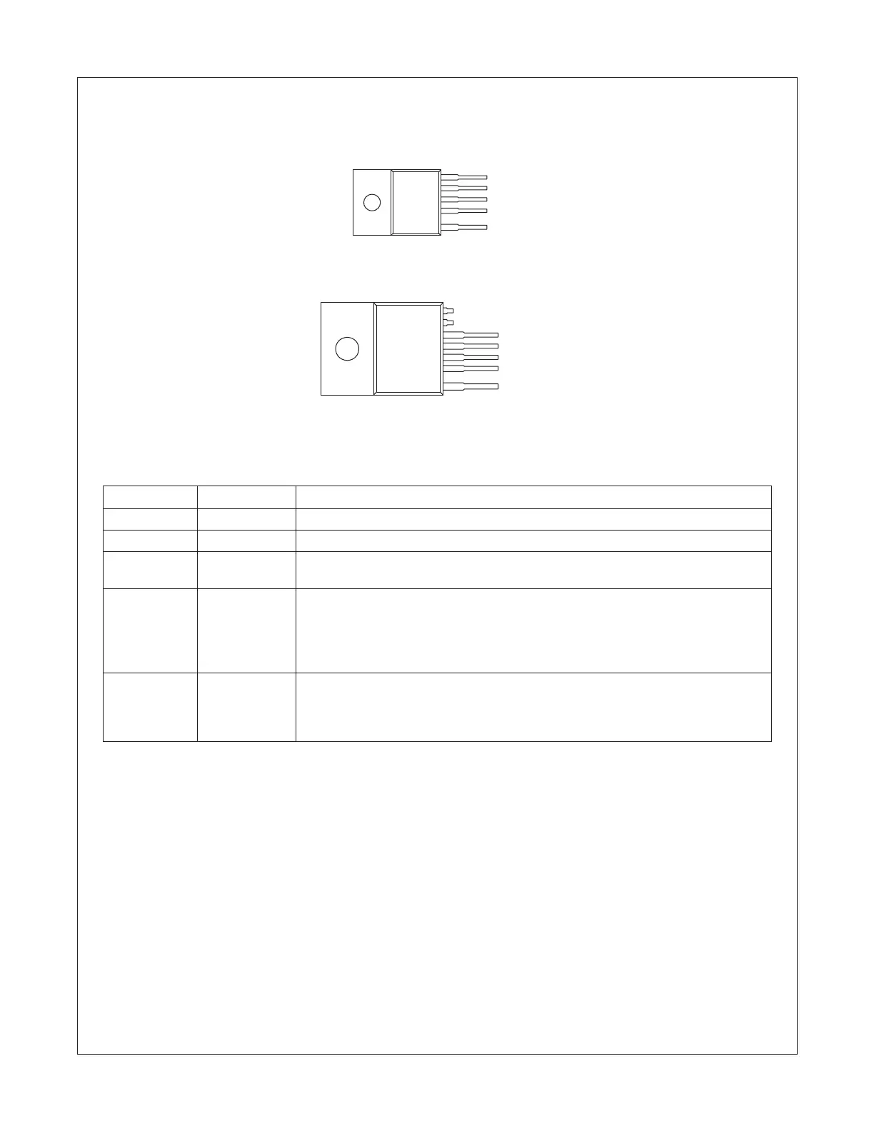
Pin Configuration
Figure 3. Pin Configuration (Top View)
Pin Definitions
Pin Number Pin Name Pin Function Description
1Drain High voltage power SenseFET drain connection.
2 GND This pin is the control ground and the SenseFET source.
3 Vcc This pin is the positive supply input. This pin provides internal operating current for
both start-up and steady-state operation.
4 Vfb This pin is internally connected to the inverting input of the PWM comparator.
The collector of an optocoupler is typically tied to this pin. For stable operation,
a capacitor should be placed between this pin and GND. If the voltage of this
pin reaches 7.5V, the over load protection triggers
,
which results in the FPS
shutting down.
5 Sync This pin is internally connected to the sync detect comparator
for quasi-resonant
switching. In normal quasi-resonant operation, the threshold of the sync
comparator is 4.6V/2.6V. Whereas, the sync threshold is changed to 3.0V/1.8V
in an extended quasi-resonant operation.
5. Sync
4. Vfb
3. Vcc
2. GND
1. Drain
TO-220F-5L
5. Sync
4. Vfb
3. Vcc
2. GND
1. Drain
TO-3PF-7L
 Loading...