Wiring Diagram
VERTICAL-HORIZONTAL INDOOR UNITS
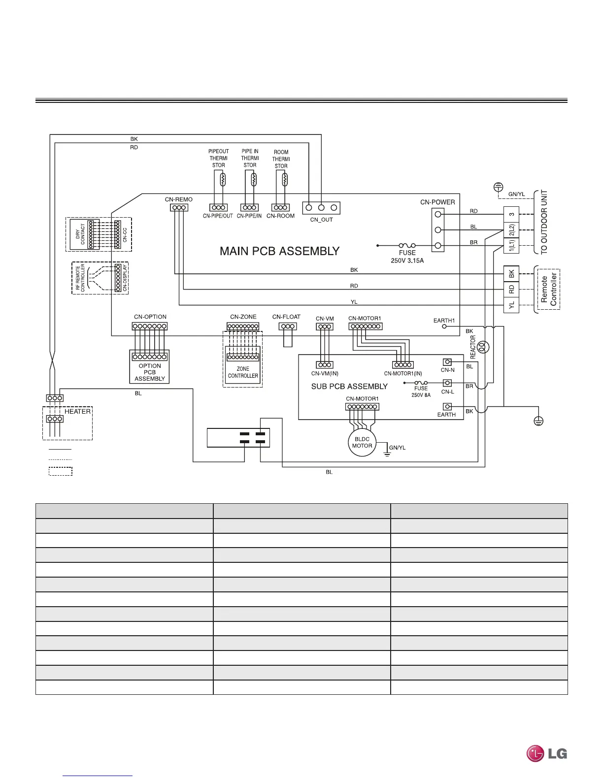
Figure 224: Multi F Vertical-Horizontal Air-Handling Indoor Unit Wiring Diagram.
: Factory Wiring
: Field Wiring
: OPTION
Connection Name Location Function
CN-POWER AC power supply AC Power line input for indoor controller
CN-MOTOR1 Fan motor output Motor output of BLDC
CN-MOTOR2 Fan motor output Motor output of BLDC
CN-FLOAT Float switch input Float switch sensing (water level sensor)
CN-PIPE/IN Suction pipe sensor Pipe in thermistor
CN-PIPE/OUT Discharge pipe sensor Pipe out thermistor
CN-ROOM Room sensor Room thermistor
CN-REMO Remote controller Remote control line
CN-OPTION Option PCB Communication between main and option
CN-ZONE Zone controller Zone control line
CN-DISPLAY RF Remote controller RF Remote control line
CN-CC Dry contact Dry contact line
Table 93: Wiring Diagram Connections.
Due to our policy of continuous product innovation, some specications may change without notication.
©LG Electronics U.S.A., Inc., Englewood Cliffs, NJ. All rights reserved. “LG” is a registered trademark of LG Corp.
162 | VERTICAL-HORIZONTAL
Multi F and Multi F MAX Indoor Unit Engineering Manual
 Loading...