Due to our policy of continuous product innovation, some specications may change without notication.
©LG Electronics U.S.A., Inc., Englewood Cliffs, NJ. All rights reserved. “LG” is a registered trademark of LG Corp.
74 | STD. WALL-MOUNTED
Multi F and Multi F MAX Indoor Unit Engineering Manual
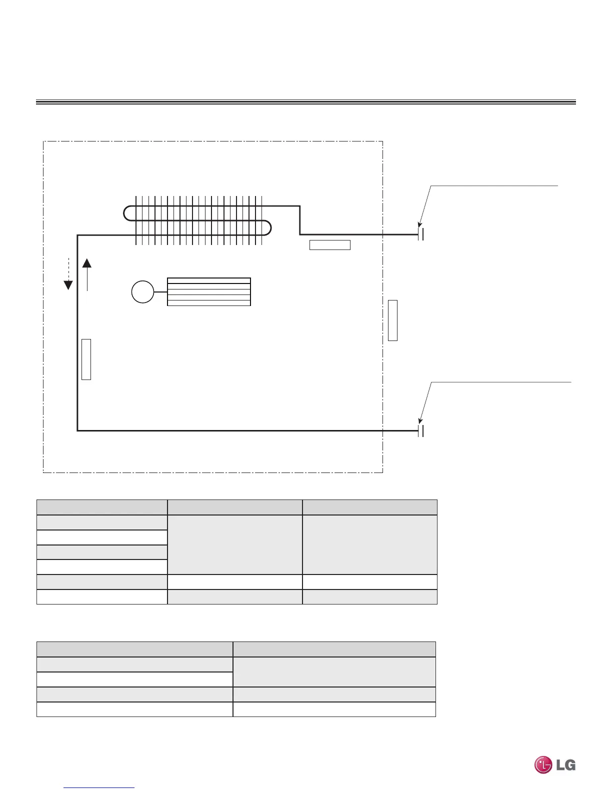
Refrigerant Flow Diagram
STANDARD WALL-MOUNTED INDOOR UNITS
Gas pipe connection port
(flare connection)
Liquid pipe connection port
(flare connection)
Cooling
Heating
Thermistor for
Evaporator Inlet Temperature
Thermistor for
Indoor Air Temperature
Thermistor for Evaporator
Outlet Temperature
Heat Exchanger
Cross Flow Fan
M
Table 36: Multi F Standard Wall-Mounted Indoor Unit Refrigerant Pipe Connection Port Diameters.
Model No. Vapor (inch) Liquid (inch)
LMN077HVT
Ø3/8 Ø1/4
LSN090HSV4
LSN120HSV4
LMN157HVT
LSN180HSV4 Ø5/8 Ø3/8
LMN247HVT Ø1/2 Ø1/4
Table 37: Multi F Standard Wall-Mounted Indoor Unit Thermistor Details.
Description (Based on Cooling Mode) PCB Connector
Indoor Air Temperature Thermistor
CN-TH1
Evaporator Inlet Temperature Thermistor
Evaporator Outlet Temperature Thermistor CN-TH2
Water Level Sensor (Optional) CN-TH3
Figure 84:Multi F Standard Wall-Mounted Indoor Unit Refrigerant Flow Diagram.
 Loading...