20
MULTI V S System Installation Manual
Due to our policy of continuous product innovation, some specifications may change without notification.
©LG Electronics U.S.A., Inc., Englewood Cliffs, NJ. All rights reserved. “LG” is a registered trademark of LG Corp.
Indoor Unit Y-Branches, continued.
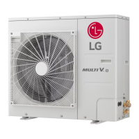
,QGRRUXQLW<EUDQFKHVPD\EHLQVWDOOHGLQKRUL]RQWDORUYHUWLFDOFRQ¿JXUDWLRQV:KHQLQVWDOOHG
vertically, position the Y-branch so the straight-through leg is within ±3° of plumb. When
installed horizontally, position the Y-branch so the take-off leg is level and shares the same
horizontal plane as the straight-through leg within ±5° rotation.
Indoor unit Y-branches must always be installed with the single port end towards the outdoor
XQLWWKHWZRSRUWHQGWRZDUGVWKHLQGRRUXQLWV7KH¿UVWLQGRRUXQLW<EUDQFKNLWPXVWEH
located at least three (3) feet from the outdoor unit. Provide a minimum of twenty (20) inches
EHWZHHQD<EUDQFKDQGDQ\RWKHU¿WWLQJVRULQGRRUXQLWSLSHGLQVHULHV
There is no limitation on the number of indoor unit Y-branches that can be installed, but there is
a limitation on the number of indoor units connected to a single outdoor unit. It is recommend-
ed that when a Y-branch is located in a pipe chase or other concealed space, access doors
should be provided for inspection access.
Figure 22: Y-branch Vertical Installation
$OLJQPHQW6SHFL¿FDWLRQ
Figure 23: +RUL]RQWDO&RQ¿JXUDWLRQ
9HUWLFDO83&RQ¿JXUDWLRQ
For Indoor Unit Y-Branches.
9HUWLFDO'2:1&RQ¿JXUDWLRQ
For Indoor Unit Y-Branches.
Figure 24: Y-branch Insulation and Pipe Detail.
Header Kits
LG Header kits are highly engineered devices designed to evenly divide the flow of refrig-
erant, and are used to join one pipe segment to two or more segments. Header kits are
intended for use where multiple indoor units are in the same vicinity and it would be better
to “home-run” the run-out pipes back to a centralized location. If connecting multiple
indoor units that are far apart, Y-branches may be more economical.
LG Header Kits Consist of:
• Two headers (one liquid line, one vapor line).
• Reducer fittings as applicable.
• 0ROGHGFODPVKHOOW\SHSHHODQGVWLFNLQVXODWLRQFRYHUV²RQHIRUWKHOLTXLGOLQHDQGRQH
for the vapor line.
Y-branches can be installed upstream between the Header and the outdoor unit, but a
Y-branch cannot be installed between a Header and an indoor unit. Headers must be in-
stalled in a horizontal and level position with the distribution ports of the fitting in the same
horizontal plane as the straight-through branch.
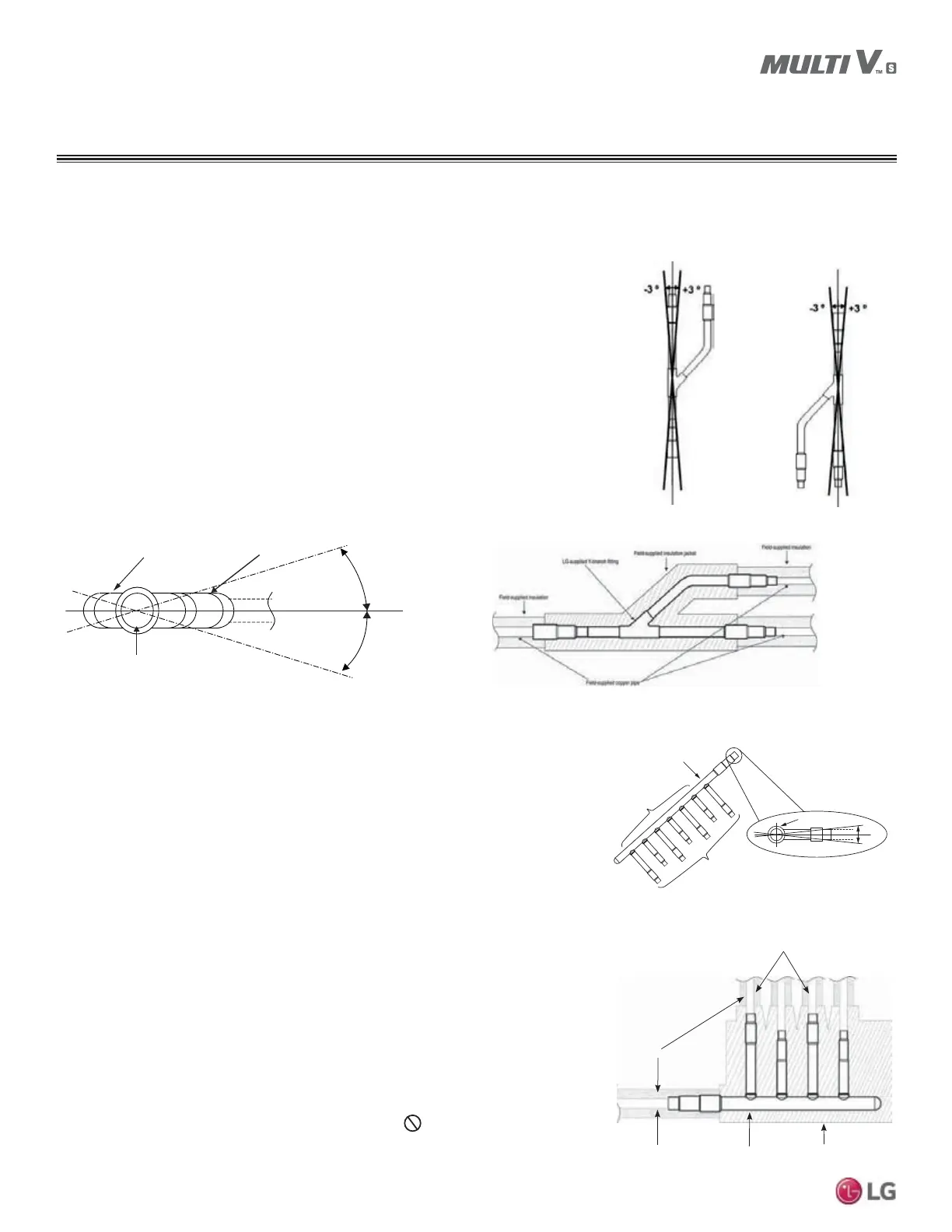
When connecting indoor units to a Header, always connect the unit with the largest nomi-
nal capacity to the port closest to the outdoor unit. Then install the next largest indoor unit
to the next port, working down to the smallest indoor unit.
Do not skip ports.
All indoor units connected to a single Header fitting should be located with an elevation
difference between indoor units that does not exceed 49 feet.
LG supplied insulation jacketLG supplied header
Field supplied copper pipe
Field supplied insulation
Field supplied copper pipe
Figure 25: +HDGHU.LW²+RUL]RQWDO5RWDWLRQ/LPLW
0XVWEH,QVWDOOHG/HYHOZLWK1R5RWDWLRQ
Figure 26: Header Insulation and Pipe Detail.
Smaller IDUs
Connect IDUs
Largest IDU
Header Inlet
Header End View
+0.0
-0.0
Piping Preparation
GENERAL INSTALLATION GUIDELINES
±5°
Horizontal Plane
±5°
Branch Leg
Straight-through Leg
Y-branch Inlet
 Loading...