48
MULTI V S System Installation Manual
Due to our policy of continuous product innovation, some specifications may change without notification.
©LG Electronics U.S.A., Inc., Englewood Cliffs, NJ. All rights reserved. “LG” is a registered trademark of LG Corp.
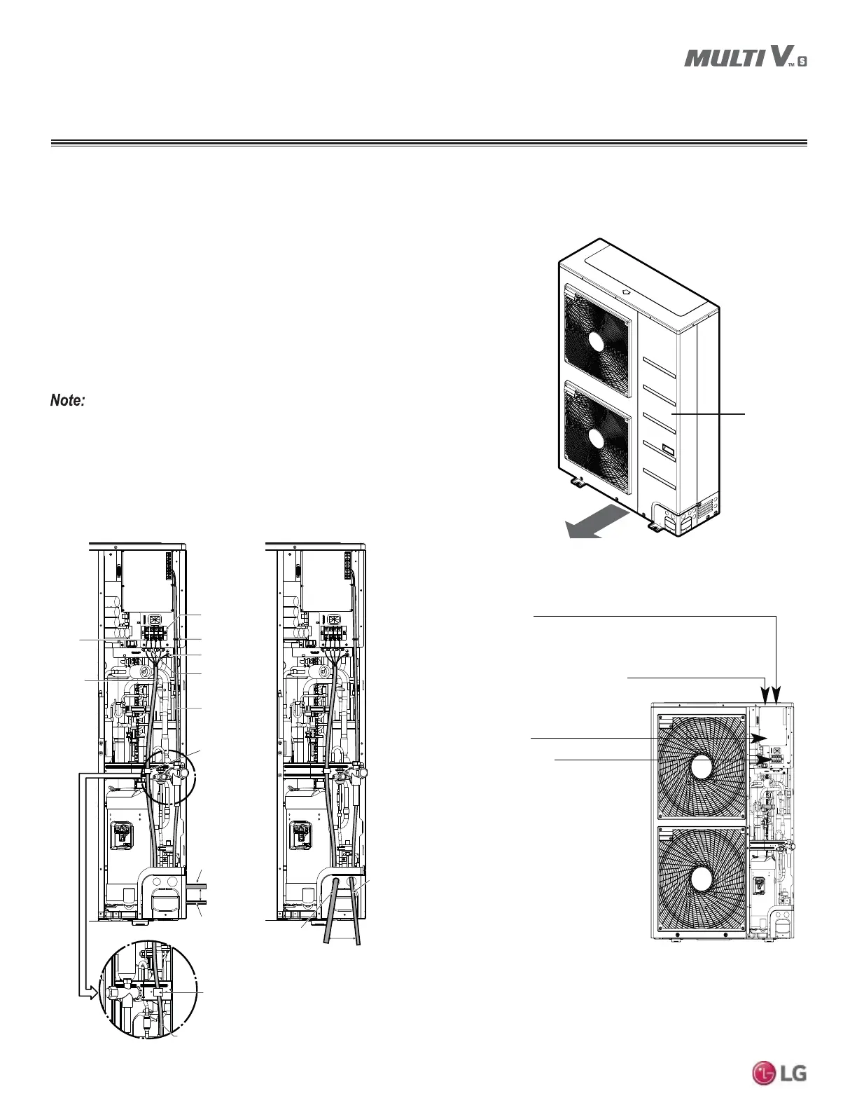
Accessing the Power Wiring and Communications Cable Connections
0XOWL962XWGRRU8QLWFRQWDLQVDWHPSHUDWXUHVHQVRUWKDWVKRXOGQRWEHH[SRVHGWRGLUHFW
sunlight. When the panel is off, cover the temperature sensor to protect it from any direct
sunlight.
Panel
Figure 54: 5HPRYLQJWKH0XOWL962XWGRRU8QLW
Access Panel.
1. Remove all of the screws that hold the side panel to the outdoor unit frame.
2. Detach panel from outdoor unit chassis by pulling the panel forward.
3. Locate the control box on the right side of the outdoor unit frame. Remove the control box
FRYHUWRDFFHVVWKH0DLQ3&%WKH,QGRRU&RPPXQLFDWLRQV3&%DQGWKH3,3&%
Outdoor unit terminal block is located immediately below the control box.
4. Connect the indoor unit to outdoor unit communication cables to the correct terminals on
the outdoor unit terminal block.
5. When connecting the indoor unit to outdoor unit communication cable with a shielded
cable, connect the ground wire to the outdoor unit ground terminal only.
Indoor Communications PCB
Main PCB
Terminal block
PI-485 PCB
(Inside the Control Box)
(Inside the Control Box)
Insulation
Sleeves
Attachment
Power / Ground Wiring
View A
Communication
Cable
More than 2
inch Gap
ODU to IDU
Communication
Cable
Power Wiring Holder
Communication
Cable
Main Power
Terminal Block
Communications
Cable Holder
Ground Wiring
Attach Firmly
A
Right Side View Front Side View
More than 2
inch Gap
Power / Ground Wiring
Power /
Ground Wiring
Communication
Cable
Attach Firmly
Figure 55: Power Wiring / Communications Cable Paths and
7HUPLQDWLRQV,QVLGHWKH0XOWL962XWGRRU8QLW
Figure 56: Locations of the Different Outdoor Unit PCBs.
WIRING
Outdoor Unit Power Wiring and Cable Connections
 Loading...