45
Refrigerant Piping Connections
Due to our policy of continuous product innovation, some specifications may change without notification.
©LG Electronics U.S.A., Inc., Englewood Cliffs, NJ. All rights reserved. “LG” is a registered trademark of LG Corp.
40 in40 in
A
B
D
F
G
B
G
D
B
H
I
J
A
E
B
I
A
B
D
C
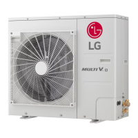
Inside wall (concealed)
Floor (fire-resistance)
Area between fire-resistant
insulation and boundary wall
Roof pipe shaft
Outside wall
Outside wall (exposed)
Sleeve
Insulation
Lagging
Caulk
Band
Water-resistant layer
Sleeve with edge
Lagging
Mortar or other fire-resistant caulk
Fire-resistant insulation
When filling an access hole with mortar, cover the
area with steel plate so that the insulation will not
fall through. For this area, use fire-resistant
materials for both the insulation and cover.
Vinyl cover should not be used.
Pipe Sleeves at Penetrations
LG requires that all pipe penetrations through walls, floors, and
pipes buried underground be routed through a properly insulated
sleeve that is sufficiently sized to provide free movement of the pipe
and does not compress the insulation. Underground refrigerant pipe
shall be routed inside a protective sleeve to prevent insulation dete-
rioration. Also follow federal, state, and local regulations and codes
when choosing a sleeve type.
Figure 49: Pipe Sleeve Options.
)RUH[DPSOH
Diameter of Gas Piping: 1/2"
Diameter of Liquid Piping: 1/4"
Thickness of Gas Piping Insulation: 0.4" x 2
Thickness of Liquid Piping Insulation: 0.4" x 2
Surplus: 0.8"
Sleeve diameter (total): 3.1" minimum
Diameter of penetrations shall be determined by pipe diameter
plus the thickness of the insulation.
$OOÀRRUDQGZDOOSHQHWUDWLRQVVKRXOGEHSURSHUO\VL]HGDQGODUJHHQRXJKWRDFFRPPRGDWHSLSHGLDPHWHUSOXVLQVXODWLRQWKLFNQHVV
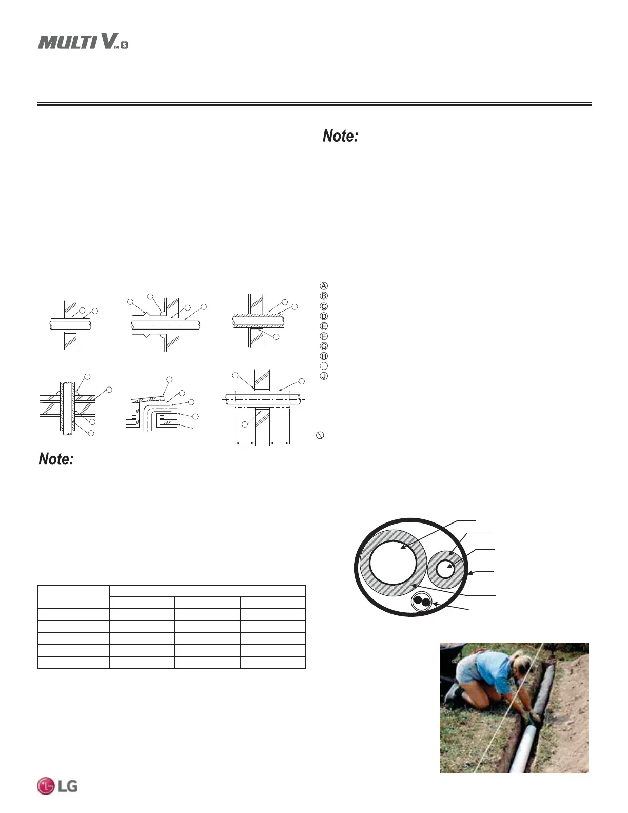
Underground Refrigerant Piping
Refrigerant pipe installed underground should be routed inside a
vapor tight protective sleeve to prevent insulation deterioration and
water infiltration. Refrigerant pipe installed inside underground
casing must be continuous without any joints. Underground refriger-
ant pipe must be located at a level below the frost line.
Figure 47: Typical Arrangement of Refrigerant Pipe and Cable(s) in a
Utility Conduit.
Table 29: Utility Conduit Sizes.
1
OD pipe diameter in inches; Values in parenthesis () indicate OD of pipe with insulation jacket.
2
Diameter of pipe with insulation. Thickness of pipe insulation is typical. Actual required thickness may vary based
RQVXUURXQGLQJDPELHQWFRQGLWLRQVDQGVKRXOGEHFDOFXODWHGDQGVSHFL¿HGE\WKHGHVLJQHQJLQHHU
3
Insulation thickness (value in parenthesis) = 3/8 inch.
4
Insulation thickness (value in parenthesis) = 1 inch.
5
Insulation thickness (value in parenthesis) = 3/4 inch.
Figure 48: Underground Refrigerant Piping.
Liquid Pipe
1
9DSRU3LSH
1
2,5
2,5
2,5
3
444
3
445
4
555
4
555
4
555
Vapor Line
Liquid Line
Min. 18 Gauge
Cable
Power/Communication
Pi
e Sleeve
Insulation Material
Insulation
Material
REFRIGERANT PIPING CONNECTIONS
Refrigerant Piping Insulation

 Loading...