71
Installation Manual
Due to our policy of continuous product innovation, some specifications may change without notification.
©LG Electronics U.S.A., Inc., Englewood Cliffs, NJ. All rights reserved. “LG” is a registered trademark of LG Corp.
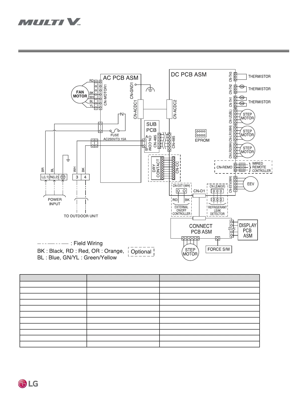
ELECTRICAL WIRING DIAGRAM
Art Cool Gallery
PCB Connection Purpose Function
CN-TH3 Pipe out thermistor Pipe out thermistor connection
CN-TH2 Pipe in thermistor Pipe in thermistor connection
CN-TH1 Return air thermistor Return air thermistor connection
CN-UD Step motor Step motor output
CN-LR1 Step motor Step motor output
CN-LR2 Step motor Step motor output
CN-REMO Wired remote controller Wired remote controller connection
CN-EEV EEV output EEV control output
CN-EXT1 External on/off controller External on/off controller connection
CN-CC Dry contact Dry contact connection
CN-485 Communication Connection between indoor and outdoor units
Table 21: Art Cool Gallery (Gen 4) SF Chassis Wiring Diagram Legend.
Figure 95: Art Cool Gallery (SF Frame) Wiring Diagram
*To enable Generation 4 features, outdoor unit DIP switch no. 3 must be set to ON. Please refer to the Multi V 5, Multi V IV, Multi V Water IV, Multi V
S Engineering Manual for additional information.
SF Frame
 Loading...