17
Installation
Due to our policy of continuous product innovation, some specications may change without notication.
©LG Electronics U.S.A., Inc., Englewood Cliffs, NJ. All rights reserved. “LG” is a registered trademark of LG Corp.
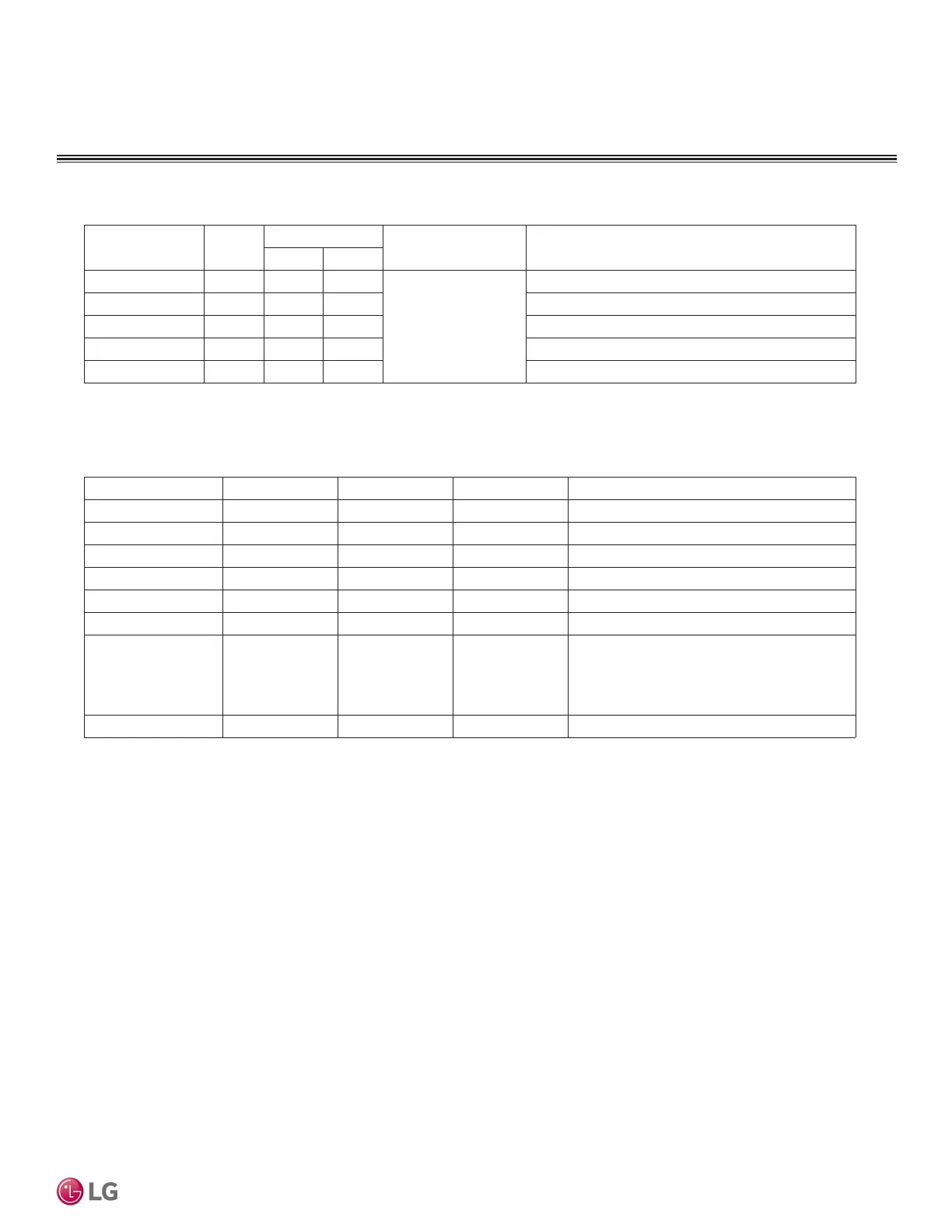
AHU COMMUNICATIONS KIT INSTALLATION
Wiring Diagram
Name Port
Value
noitcnuF.cepS lacirtcelE
Short Open
On/Off DO2 On Off
12 VDC / 1 A,
250 VAC / 3 A
Operation On/Off status
sutats tsorfeD UDOlamroNtsorfeD3ODtsorfeD
sutats ffO/nO noitarepo rosserpmoCffOnO4ODsutatS .pmoC
---5ODdevreseR
---6ODdevreseR
noitcnuF.cepS lacirtcelEeulaVtroPemaN
---1IUdevreseR
---2IUdevreseR
---3IUdevreseR
---4IUdevreseR
---5IUdevreseR
---6IUdevreseR
Capacity Control¹
0~10V
UI7
(AI)
0~10 V Input
DC 0~10 V,
20 mA
ODU Capacity control input(0~10 V)
*When Temp. Control Type is ‘Manual by
DDC’(SW 1-2 : Off), refer to UI7 Analog Input
---8IUdevreseR
1. Refer to the Capacity Control (UI7) combination ratio table.
2. UI is available when Dip SW1-1 is Off
Table 11: Digital Output
Table 12: Universal Input
 Loading...