078 079
_
COMPREHENSIVE APPLICATION AND INSTALLATION MANUAL
LG Electronics
Installation check listConguration
System Design ApplicationsIntroduction
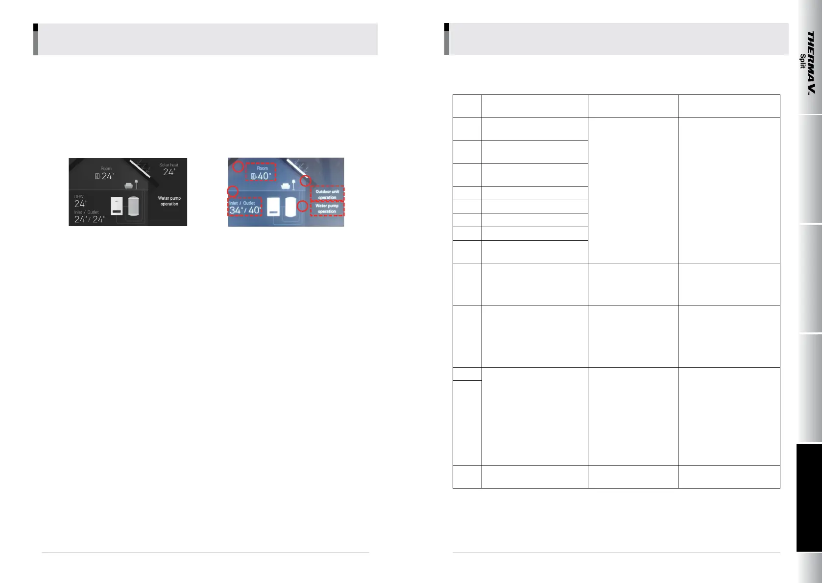
• Initiating operation mode
Normal operation is conrmed if you can check whether outdoor unit and water pump are operating on
the display of remote controller after starting heating or cooling operation and
if average temperature difference of 5 °C between entering and leaving water is conrmed..
Average temperature difference higher than 7 °C means lack of ow - check conditions of strainer and
if air is released.
1
2
3
4
1) Air temperature is displayed after selecting room temperature. See if air temperature appropriate for
the site is displayed.
2) See if average temperature difference between entering and leaving water is 5 °C - Check ow if
difference is higher than 7 °C
3) See if outdoor unit is actually running when "Outdoor unit operation" is displayed
4) See if water pump is actually running when "Water pump operation" is displayed
2.1 Error codes
Code
No.
Description Cause Normal Condition
1
Problem in remote room air
sensor
• Incorrect connection
between sensor and
PCB(Heater)
• PCB(Heater) fault
• Sensor fault
• Resistance: 10 kΩ at 25 °C
(unplugged) → for Remote
room air sensor
• Resistance: 5 kΩ at 25 °C
(unplugged) → for all sen
-
sors EXCEPT remote room
air sensor
• Voltage: 2.5 V DC at 25 °C
(plugged) (for all sensors)
• Refer resistance-temper-
ature table to check in
different temperature
2
Problem in refrigerant (inlet
side) sensor
6
Problem in refrigerant (outlet
side) sensor
8 Problem in water tank sensor
16 Problem in sensors
17 Problem in water-inlet sensor
18 Problem in water-outlet sensor
19
Problem in water-interim
sensor
10 BLDC Water Pump Lock
• Restriction of BLDC
Water pump
• Defected BLDC Water
pump / abnormal assembly
condition
• Fan lock by foreign material
3
Bad communication between
remote controller and unit.
• Incorrect connection
between sensor and
PCB(Heater)
• PCB(Heater) fault
• Sensor fault
• Wire connection between
remote controller and Main
PCB assembly(Heater)
should be tight
• Output voltage of PCB
should be 12 V DC
5
Bad communication between
Main PCB assembly(Heater)
and Main PCB
assembly(Inverter) of the unit
• The connector for trans
-
mission is disconnected
• The connecting wires
are misconnected
• The communication line
is broken
• Main PCB assembly
(Inverter) is abnormal
• Main PCB assembly
(Heater) is abnormal
• Wire connection be-
tween remote control
panel and Main PCB
assembly(Heater) should
be tight
53
9 PCB program (EEPROM) fault
• Electrical or mechanical
damage the EEPROM
• This error can not be
permitted