41
5-2. Door Lock Switch Assembly.
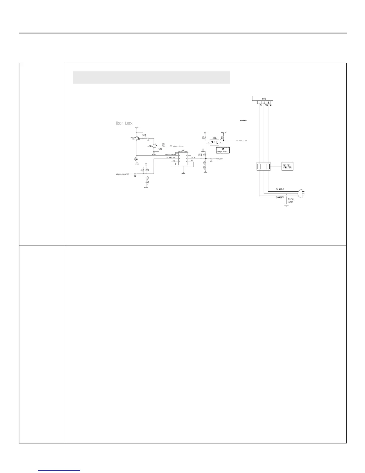
Wiring
diagram
Function
Circuit in the MAIN PCB / Wiring Diagram
The Door Lock Switch Assembly consists of a Solenoid, Plunger, Level, Key,
Sol-spring and Micro Switch. It locks the door during a wash cycle.
1. Door lock operation
- When a cycle is started, the PCB sends the door lock signal if Reed switch detects that the door
is closed.
- 16.5V is supplied to Solenoid.
- Magnetic force that is caused by solenoid operation inserts Plunger into Solenoid.
- The Level that connected with plunge is pushed out the key.
- The key must be in the proper position for the PCB to sense that the door is locked, otherwise the
dL error code will be displayed.
- If the latch does not extend far enough, the PCB will display the dL error code. This can happen,
for example, if the solenoid does not operate.
Note: The door will attempt to lock 3 times. If it does not successfully lock, the solenoid will drive
the latch to the open position.
2. Door unlock operation
- When the cycle ends, or if the cycle is paused, the PCB sends an unlock pulse to the solenoid.
-The key will attempt to unlock three times. If it fails to sense that the door is unlocked,
the solenoid will be driven to the lock position.

 Loading...