English
22
HIMOD−C
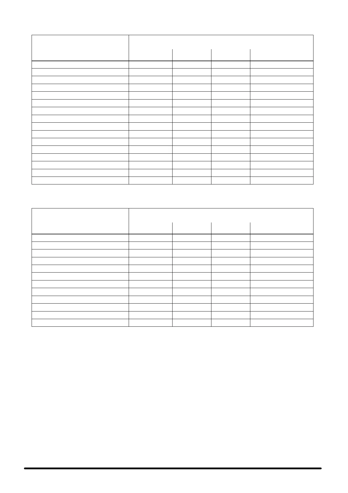
Tab. 6 − Electrical data
50 Hz
component
FAN
(3ph − 160 400V)
Model
OA
(A)
FLA
(A)
LRA
(A)
absorbed power
(kW)
27U C 4.3 4.4 16 1.4
45U C 4.3 4.4 16 1.4
55U C 2 x 4.3 2 x 4.4 2 x 16 2 x 1.5
65U C 2 x 4.3 2 x 4.4 2 x 16 2 x 1.5
80U C 2 x 4.3 2 x 4.4 2 x 16 2 x 1.5
85U C 2 x 4.3 2 x 4.4 2 x 16 2 x 1.5
90U C 2 x 5.8 2 x 6.0 2 x 17.8 2 x 2.4
10U C 2 x 5.9 2 x 6.0 2 x 17.8 2 x 2.6
12U C 3 x 5.9 3 x 6.0 3 x 17.8 3 x 2.5
14U C 3 x 5.9 3 x 6.0 3 x 17.8 3 x 3.1
27O C 4.3 4.4 16 1.5
45O C 4.3 4.4 16 1.5
55O C 2 x 4.3 2 x 4.4 2 x 16 2 x 1.5
65O C 2 x 4.3 2 x 4.4 2 x 16 2 x 1.5
80O C 2 x 4.4 2 x 4.4 2 x 16 2 x 1.6
85O C 2 x 4.4 2 x 4.4 2 x 16 2 x 1.6
60 Hz
component
FAN
(3ph − 160 460V)
Model
OA
(A)
FLA
(A)
LRA
(A)
absorbed power
(kW)
27U C 3.4 3.5 16 1.1
45U C 3.4 3.5 16 1.2
55U C 2 x 3.3 2 x 3.5 2 x 16 2 x 1.2
65U C 2 x 3.4 2 x 3.5 2 x 16 2 x 1.2
80U C 2 x 3.2 2 x 3.5 2 x 16 2 x 1.2
85U C 2 x 3.3 2 x 3.5 2 x 16 2 x 1.2
27O C 3.3 3.5 16 1.2
45O C 3.3 3.5 16 1.2
55O C 2 x 3.3 2 x 3.5 2 x 16 2 x 1.2
65O C 2 x 3.3 2 x 3.5 2 x 16 2 x 1.2
80O C 2 x 3.3 2 x 3.5 2 x 16 2 x 1.3
85O C 2 x 3.3 2 x 3.5 2 x 16 2 x 1.3
1. The fan OA" value and the absorbed power are refered to standard air flow; Under unit with underflow air discharge and 20 Pa available exter-
nal static pressure; Over unit with ducted air discharge and 50 Pa available external static pressure.
NOTE: the indicated fan currents are measured on their terminal boards; to calculate the current absorption of the fans to the machine supply
terminals multiply the indicated values by the selected transforming ratio (see Tab. 4).
 Loading...


