REV : 5
REV DATE : 12/16
DPN002946
Page :1 /1
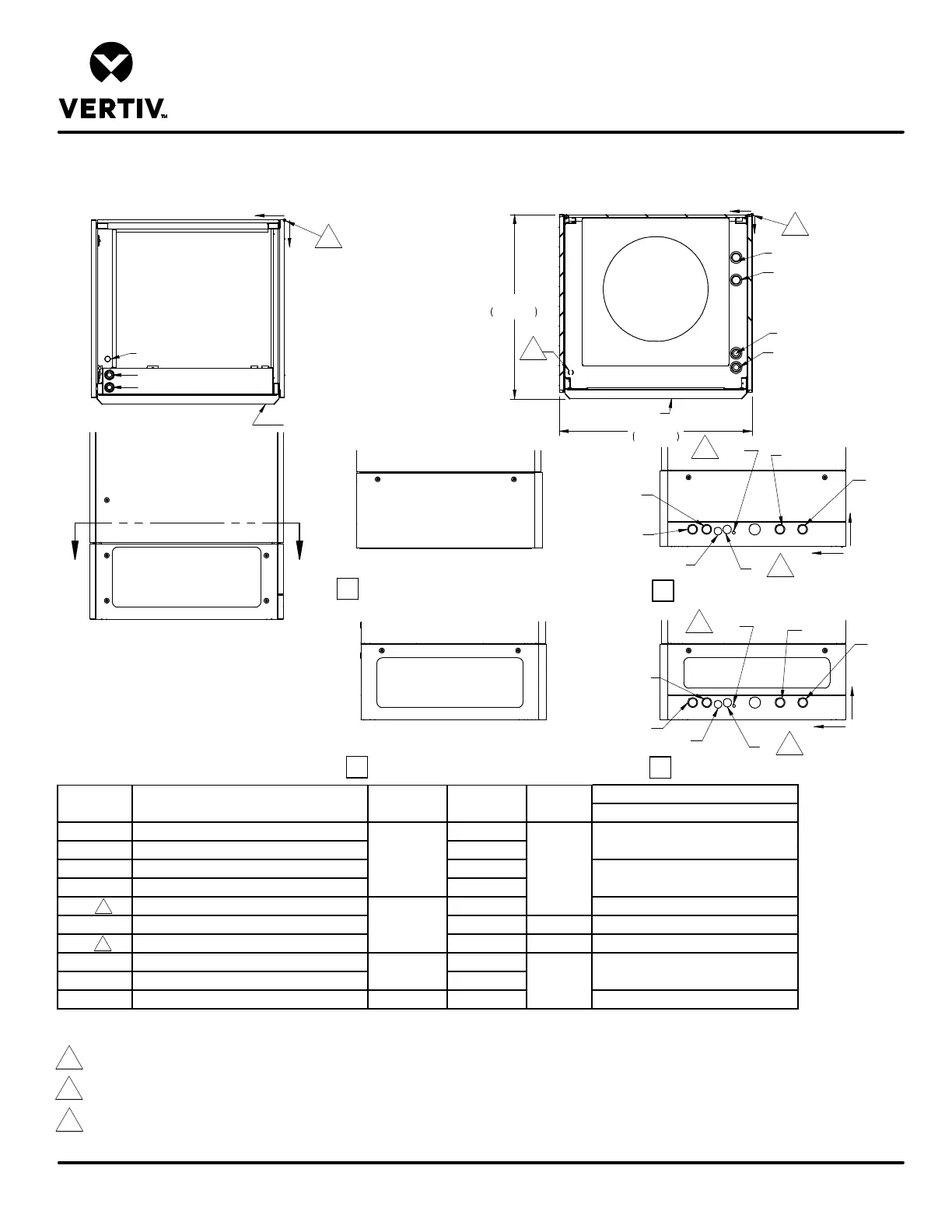
DOWNFLOW FRONT DISCHARGE MODELS
Form No.: DPN001040_REV4
PRIMARY CONNECTION LOCATIONS
LIEBERT PCW
34 1/2"
876mm
32 15/16"
837mm
FRONT OF UNIT
HWS
HWR
FRONT OF UNIT
E2
E1
LV1
X
Y
O
TOP VIEW
X
Y
O
SECTION A-A
WS
WR
WITHOUT LEFT SIDE DISCHARGE
WITH LEFT SIDE DISCHARGE
WITHOUT RIGHT SIDE DISCHARGE
WITH RIGHT SIDE DISCHARGE
A A
FRONT VIEW
WR
CE
CD
HUM
WS
HWR
HWS
Y
Z
Y
Z
HWS
HWR
WR
HUM
CE
CD
WS
Notes:
1. Pipes at various heights to allow for tube cutter to be used. Will require stub tubes and elbows for connection at all tube locations.
2. Humidifier supply line will need to be routed through this opening to the connection at the left hand side of the unit.
3. Drawing not to scale. All dimensions from rear corner of unit including panels, and have a tolerance of ± 1/2" (13mm).
4. Field pitch Condensate Drain line a minimum of 1/8" (3.2 mm) per foot (305 mm). All units contain a factory installed condensate trap. Do not trap external to the unit.
Drain line may contain boiling water. Select appropriate drain system materials. The drain line must comply with all local codes.
5. All water piping is O.D. Copper except as noted.
HOT WATER REHEAT RETURN (OPTIONAL)
HOT WATER REHEAT SUPPLY (OPTIONAL)
CONDENSATE DRAIN
CONDENSATE ELECTRICAL
ELECTRICAL CONN. (HIGH VOLT) TOP
ELECTRICAL CONN. (HIGH VOLT) TOP
ELECTRICAL CONN. (LOW VOLT) TOP
CONNECTION SIZE / OPENING
1-1/8"
POINT DESCRIPTION X in. (mm) Y in. (mm) Z in. (mm)
N/A
7/8”, 1-3/8”, 1-3/4”
5/8"
2-7/8 (73)
31-1/4 (793)
3 (76)
N/A
4
2
2
2
2
4
4
ELECTRICAL TOP
CONNECTIONS
3
3