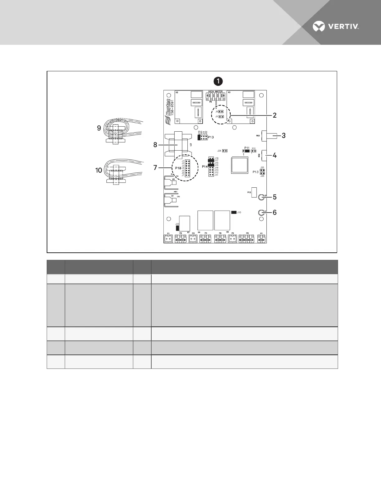
Figure 9.13 Steam-generating Humidifier Circuit board diagram
Item Description Item Description
1 PCB is configured for: MES-L 6 Yellow LED
2
HW Sensor Jumperss
• J9: Low Voltage
200-240V
• J8: High Voltage
380-600V
7
Mains Voltage Select Jumpers
• J6: 200-208
• J5: 230V
• J3: 380-415
• J2: 460V
• J1: 575V
3
Capacity adjust (Default at
100%)
8 Current transformer
4 Sealed, do not adjust 9
Current Transformer for MES-L10, loop current-sensing wire twice through current sensing
coil.
5 Green LED 10
Current transformer for MES-L20, loop current-sensing wire once through current-sensing
coil.
To configure the correct PCB voltage, set the jumpers as follows:
NOTE: The asterisk (*) indicates a factory setting. Do not adjust.
• 208V: J6, J9, J15*, J17*, J19*, J10*, J23*, P11 (2-3)*
• 230V: J5, J9, J15*, J17*, J19*, J10*, J23*, P11 (2-3)*
• 380V: J3, J8, J15*, J17*, J19*, J10*, J23*, P11 (2-3)*
• 460V: J2, J8, J15*, J17*, J19*, J10*, J23*, P11 (2-3)*
• 575V: J1, J8, J15*, J17*, J19*, J10*, J23*, P11 (2-3)*
Vertiv | Liebert® PDX™ and PCW™ Installer/User Guide | 82