B.- Programming variables
The following functions are implemented for these variables:
Function 04: reading logs.
Function 10: Writing multiple logs.
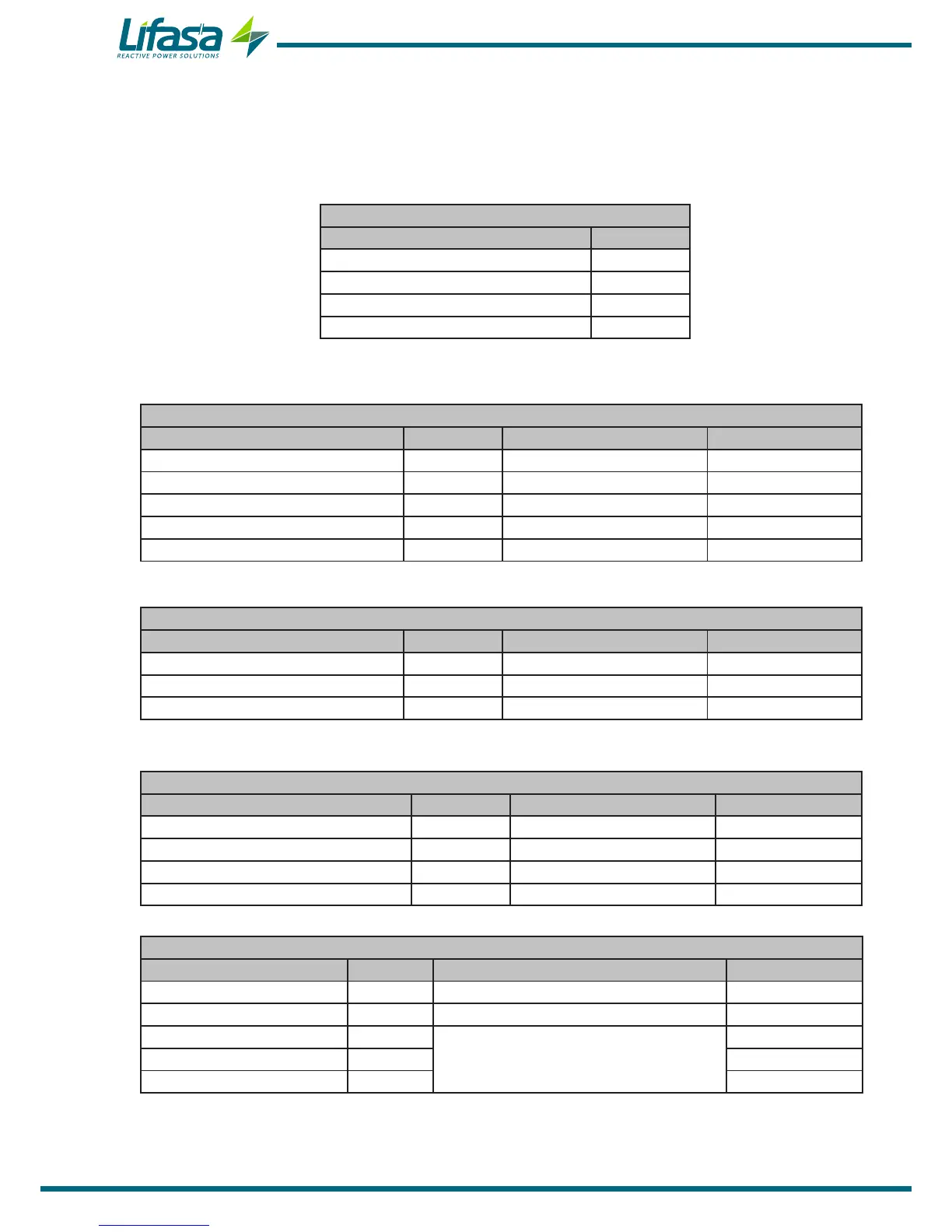
Table 15:Modbus memory map: programming variables (Table 1)
Unit parameters
Configuration variable Address
Serial number
(1)
1000-1003
Frame number
(1)
1010-1013
Version
(1)
1020-1021
Hardware log
(1)
1030-1033
(1)
The parameters of the unit have only implemented function 04.
Table 16:Modbus memory map: programming variables (Table 2)
RS-485 Communications
Configuration variable Address Valid data margin Default value
Peripheral no. 1071 1 to 254 1
Speed 1072 0 (9600), 1 (19200) 1
Parity 1073 0 (none), 1 (odd), 2 (even) 0
Length 1074 0 (8 bits), 1 (7 bits) 0
Stop bits 1075 0 (1 bits), 1 (2 bits) 0
Table 17:Modbus memory map: programming variables (Table 3)
CPC-NET communications
Configuration variable Address Valid data margin Default value
Speed 1082 0 (9600), 1(19200), 2(38400) 2
Parity 1083 0 (none), 1 (odd), 2 (even) 0
Stop bits 1085 0 (1 bits), 1 (2 bits) 0
Table 18:Modbus memory map: programming variables (Table 4)
Transformation ratios
Configuration variable Address Valid data margin Default value
Current primary 1090 1 - 10000 5
Current secondary 1091 0 (1 A), 1 (5 A) 1
Voltage primary 1092-1093 1 -99999 1
Voltage secondary 1094-1095 1 -99999 1
Table 19:Modbus memory map: programming variables (Table 5)
Connection type
Configuration variable Address Valid data margin Default value
Connection type 1100 0 (3U.3C), 1 (3U.1C), 2 (2U.1C) 0
Phase
(1)
1101 1 to 6 (Table 41) 1
Current 1
/ 1 / 2
1102
1 (Phase 1 direct), 2 (Phase 2 direct),
3 (Phase 3 direct), 4 (Phase 1 reverse),
5 (Phase 2 reverse), 6 (Phase 3 reverse),
1
Current 2
(1)(2)
1103 2
Current 3
(1)(2)
1104 3
(1)
Only used when the connection type is other than 3U.3C.
(2)
Indicates the relationship between the assigned voltage and the current direction.
Example: If you see Current 1 = 1, Current 2 = 5 and Current 3 = 3, this means that:
64