Current 1 is assigned to voltage 1 in the direct direction, current 2 is assigned to voltage 2 in the reverse
direction and current 3 is assigned to voltage 3 in the direct direction.
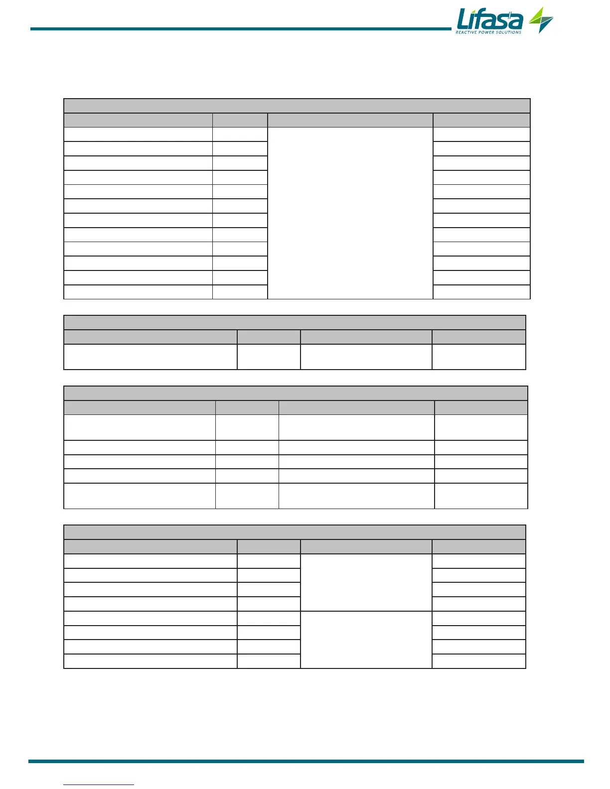
Table 20:Modbus memory map: programming variables (Table 6)
Status of the stages
Configuration variable Address Valid data margin Default value
C1 1110
0 (Auto),
1 (On),
2 (OFF),
3 (OnNc)
0
C2 1111 0
C3 1112 0
C4 1113 0
C5 1114 0
C6 1115 0
C7 1116 0
C8 1117 0
C9 1118 0
C10 1119 0
C11 111A 0
C12 111B 0
Table 21:Modbus memory map: programming variables (Table 7)
Voltage level
Configuration variable Address Valid data margin Default value
Voltage level
1121 0 (Low voltage)
1 (Medium/High voltage)
0
Table 22:Modbus memory map: programming variables (Table 8)
Display
Configuration variable Address Valid data margin Default value
Lighting (Backlight)
1125 0 (Comes on when pressing a key)
1 (ON), 2 (OFF)
0
Lighting level 1126 0 -10 (Value % / 10) 7
Language 1127 0 (Spanish), 1 (English), 2 (French) 0
Advanced setup 1128 0 (OFF), 1 (ON) 0
Analogue bar 1129 0 (No), 1 (Current), 2 (ITHD)
3 (Connected power)
0
Table 23:Modbus memory map: programming variables (Table 9)
Target cos φ
Configuration variable Address Valid data margin Default value
Target cos φ 1 1130
0 - 100 (Value x 100)
100
Target cos φ 2 1131 100
Target cos φ 3 1132 100
Target cos φ 4 1133 100
Target cos φ 1 type 1134
0 (Capacitive)
1 (Inductive)
1
Target cos φ 2 type 1135 1
Target cos φ 3 type 1136 1
Target cos φ 4 type 1137 1
65