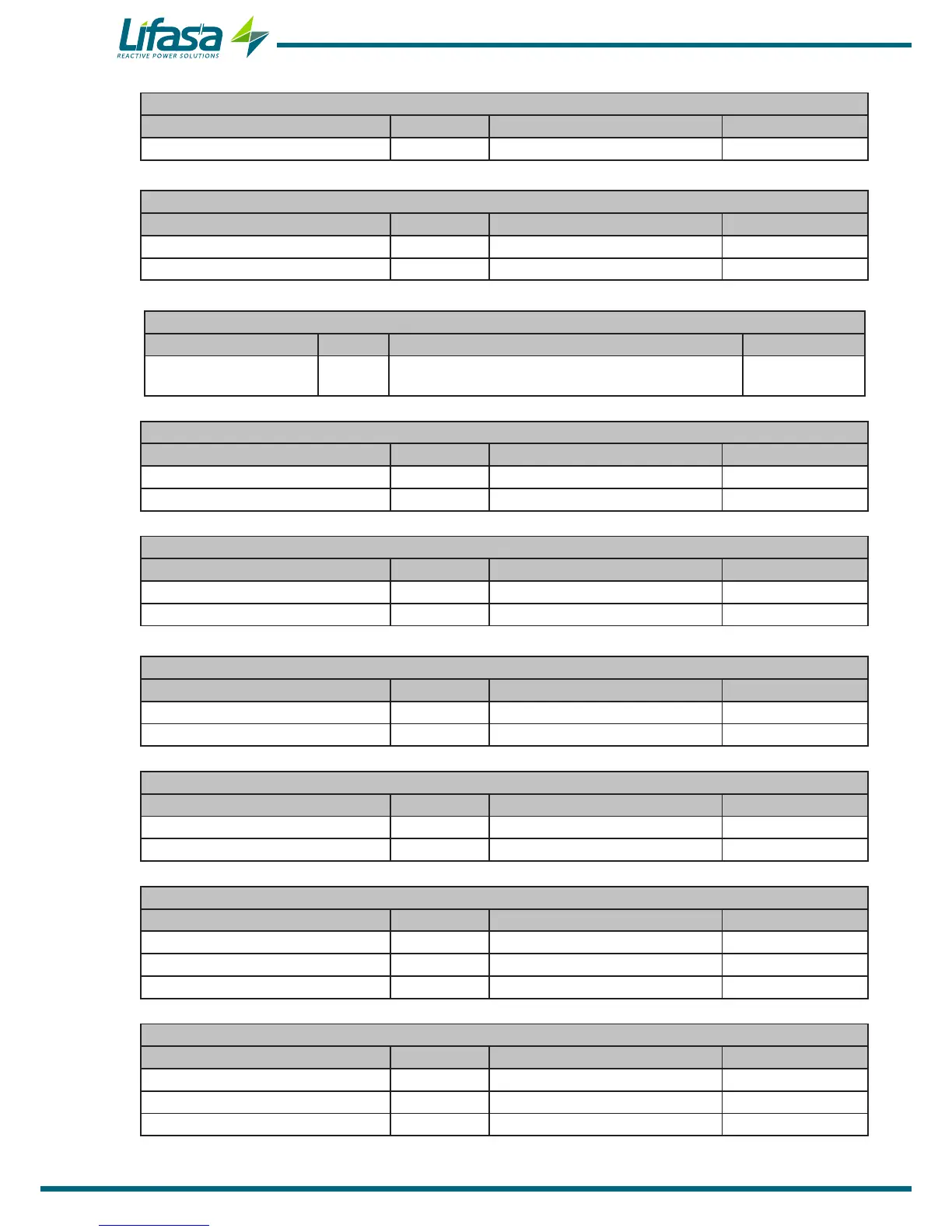
Table 24:Modbus memory map: programming variables (Table 10)
C/K factor
Configuration variable Address Valid data margin Default value
C/K factor 1138 0 - 100 (Value x 100) 100
Table 25:Modbus memory map: programming variables (Table 11)
Program
Configuration variable Address Valid data margin Default value
Program 1139 1111-1999 1111
Operation type 113A 0(FCP), 1(Total), 2(Sim) 0
Table 26:Modbus memory map: programming variables (Table 12)
No� of stages
Configuration variable Address Valid data margin Default value
No. of stages 113B
0-6 (Controller MASTER control VAR FAST 6)
0-12 (Controller MASTER control VAR FAST 12)
6
12
Table 27:Modbus memory map: programming variables (Table 13)
Connection and reconnection time
Configuration variable Address Valid data margin Default value
Connection time 113C 0-999 network cycles 10
Reconnection time 113D 0-999 network cycles 50
Table 28:Modbus memory map: programming variables (Table 14)
Alarm: Voltage THD
Configuration variable Address Valid data margin Default value
Low Value 1140 0 - 100 % 5
Hi Value 1141 0 - 100 % 10
Table 29:Modbus memory map: programming variables (Table 15)
Alarm: Current x I THD
Configuration variable Address Valid data margin Default value
Low Value 1142 0 - 100 % 4
Hi Value 1143 0 - 100 % 5
Table 30:Modbus memory map: programming variables (Table 16)
Alarm: Temperature
Configuration variable Address Valid data margin Default value
Low Value 1144 0 - 80 ºC 55
Hi Value 1145 0 - 80 ºC 70
Table 31:Modbus memory map: programming variables (Table 17)
Alarm: Leakage Current
Configuration variable Address Valid data margin Default value
Search for the responsible stage 1146 0 (OFF), 1 (ON) 0
Value 1147 10 - 1000 mA 300
Stages enabled 1148 0 (No), 1 (Yes) 0
Table 32:Modbus memory map: programming variables (Table 18)
Alarm: Cos φ
Configuration variable Address Valid data margin Default value
Value of Cos φ 1149 80 -100 (Value x 100) 95
Current value 114A 0 - 9999 A 20
Type of Cos φ 114B 0 (Capacitive), 1 (Inductive) 1
66