www.lifebreath.com 11
DRAIN CONNECTIONS
The HRV cabinet has pre-punched holes for the drain. The HRV may produce some condensation
during a defrost cycle. This water should flow into a nearby drain or be taken away by a condensate
pump.
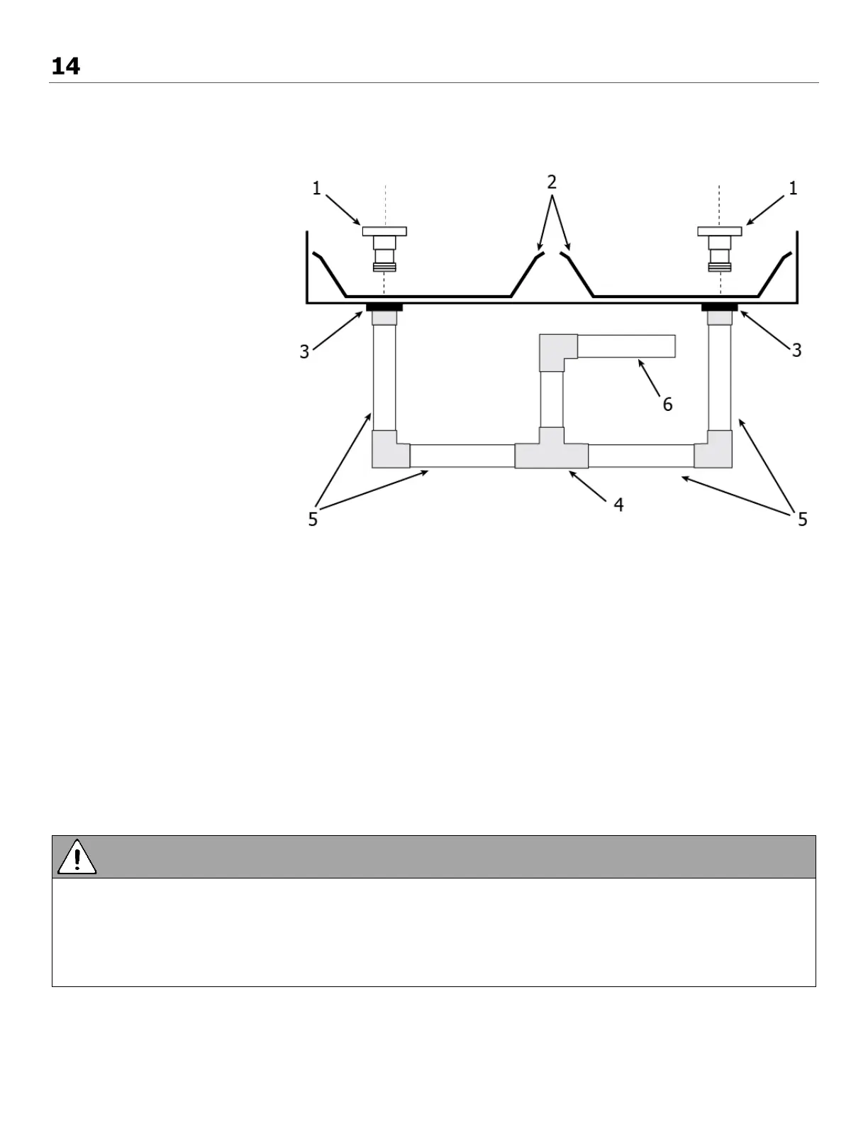
Installation:
(1) Drain Spout
(2) Drain Pan
(3) Drain Spout Nut
(4) Tee Connector
(5) 1/2 in. Rigid Tubing
(6) Drain Line
Steps:
1. Insert the drain spout through the hole in the drain pan.
2. Install the nut onto the drain spout. Tighten the nut.
3. Construct a P-trap using the plastic tee connector.
4. Using appropriate fittings (not included), connect 1/2 in. rigid tubing (not included) to the tee
connector and connect the other end to the drain spouts.
5. Position the tee connector to point upward and connect the drain line.
6. Tape or fasten base to avoid any kinks.
7. Pour a cup of water into the drain pan of the HRV after the drain connection is complete. This creates a
water seal which will prevent odours from being drawn up the hose and into the fresh air supply of the
HRV.
• The HRV and all condensate lines must be installed in a space where the temperature is maintained
above the freezing point or freeze protection must be provided.
• Drain trap and tubing must be below bottom of door with 1/4 in. per foot downwards slope away
from unit.
• A secondary drain pan may be required to protect from condensate leakage.