www.lifebreath.com
Page 14
FAN DEFROST (ALL UNITS)
The 1500I/E-ECM, 2000IFD/EFD, and 2500IFD/EFD units are equipped with an electronically controlled fan
defrost system to remove frost that collects on the warm air side of the aluminum heat transfer surfaces of the
heat exchanger core. When the outside temperature drops below 27ºF (-3ºC), a defrost timer is activated
which provides for an automatic defrost cycle. During the automatic defrost cycle, the fresh air supply is shut
off while the exhaust fan continues to operate. This allows warm inside air to flow over the heat exchanger
core, melting any frost accumulation. After the defrost period, the fresh air supply fan automatically returns to
the normal speed and fresh outside air continues to be drawn into the building. Water from the melted frost
collects in the bottom drip pans and drains out through the bottom drain connections. The defrost cycle
repeats automatically until the outdoor air temperature rises above 27ºF (-3ºC).
• If the indoor air temperature is too low, the defrost time may need to be increased.
• The unit must be mounted level (horizontal) to obtain proper drainage of water from the heat
exchange cores and drip pans. The warranty will be void if these conditions are not met.
Defrost Time Adjustment
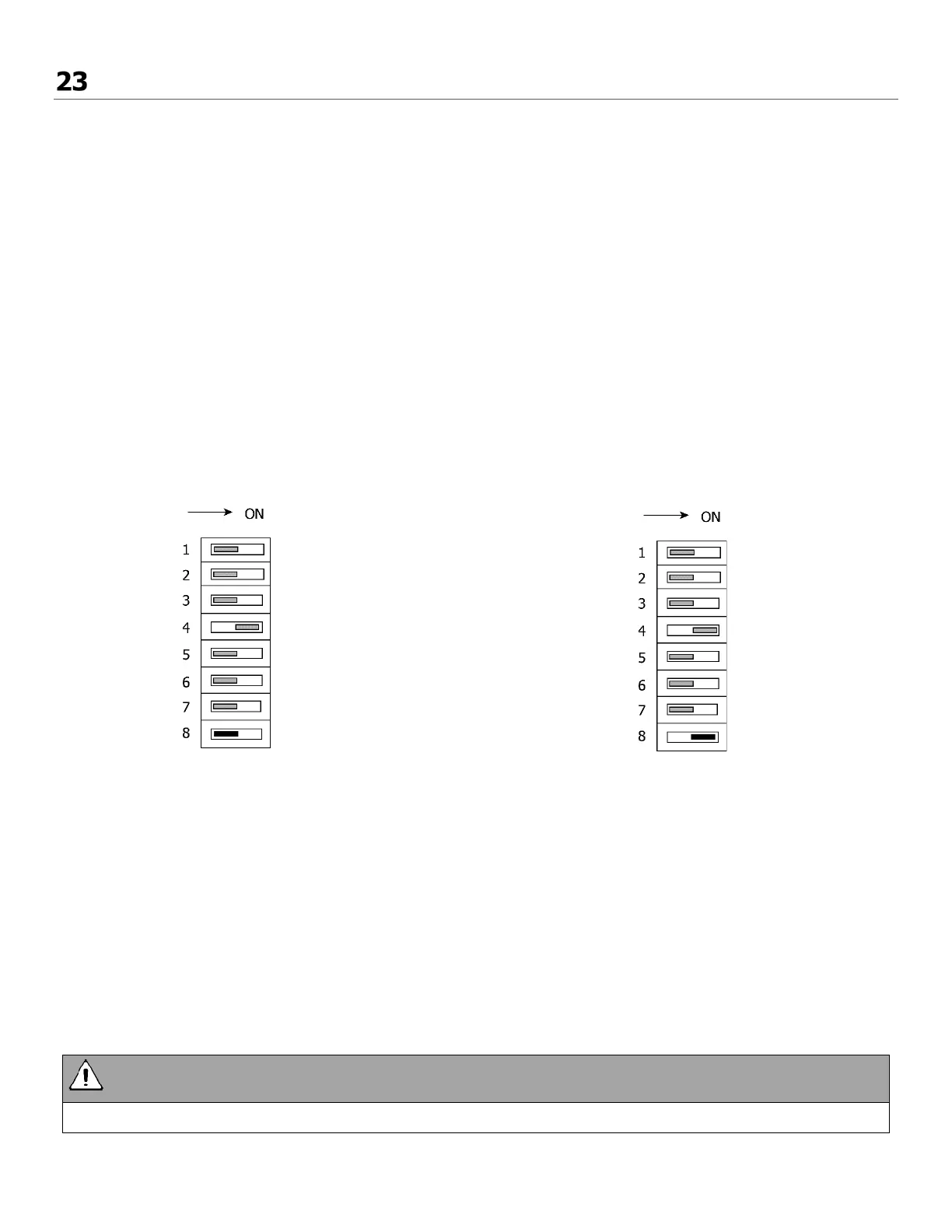
DIP switch #8 (located on the Aircom circuit board) will adjust the defrost time. Do not change to any other
DIP switch configuration.
Factory Setting (DIP switch #8 OFF)
The sequence of events for this defrost mode at
27°F (-3°C) is:
1. Both fans will stop for one minute.
2. The HRV exhaust motor will initiate and
operate for 4 minutes.
3. Both HRV motors (exhaust and intake)
will operate for 30 minutes.
4. The cycle repeats.
Increased Defrost Time (DIP switch #8 ON)
Cooler climates may require a more aggressive
defrost cycle:
1. Both fans will stop for one minute.
2. The HRV exhaust motor will initiate and
operate for 4 minutes.
3. Both HRV motors (exhaust and intake)
will operate for 20 minutes.
4. The cycle repeats.
• Change DIP switch only as illustrated on this page. Do not adjust any other switches.