Netlink Installation and Operation Manual
4 5
Installation and Operation
1.3.1 Making the Power Connections to the Netlink
DC Systems ONLY
In a DC system, the DC power source for the Netlink is con-
nected to the INPUT (V+ & V-) fastons or terminals. The
voltage of this source must be between 8 and 30VDC and
should be backed up with a battery set or UPS to maintain
communication during a loss of primary AC voltage.
The power connections for the Netlink must connect directly
to the DC1 output or the V+/V- faston connectors (if present)
of the FPO power supply. (Figure 1.4)
i Note: Do not power the Netlink through another accesso-
ry board's output or from the B1/B2 connectors. (Figure 1.5)
AC Systems
i WARNING - DO NOT CONNECT AC POWER TO THE Net-
link BOARD'S INPUT (V+ & V-) TERMINALS OR DAMAGE
TO THE Netlink WILL OCCUR.
In an AC system, power to the Netlink board MUST be sup-
plied by an NS2 board, which is sold separately. See Ap-
pendix 2 for more information.
1.3.2 Making the Ethernet Connection to the Netlink
Plug the Ethernet cable into the RJ45 jack on the Netlink
until the locking tab clicks. Connect the other end of the
Ethernet cable to the network.
i Note: This port does not accept PoE power. Do not con-
nect PoE to this port.
i Note: The Netlink board should be configured via a di-
rect connection to a laptop or PC before connecting to the
network. See the Initial Configuration Section (Section 2) of
this manual for more details.
1.3.3 Connecting Devices to be Monitored to the Netlink
Connect one end of the SPI cable to one of the "Device" con-
nectors on the Netlink. Connect the other end to the Data-
Link (DL) connector of the device to be monitored (such as
an FPO - see the manual for the device being connected for
the location of the DL connector). If monitoring more than
one device, repeat this process for devices 2 through 8 as
appropriate. Note that both ends of these cables are keyed
and will only plug in one direction.
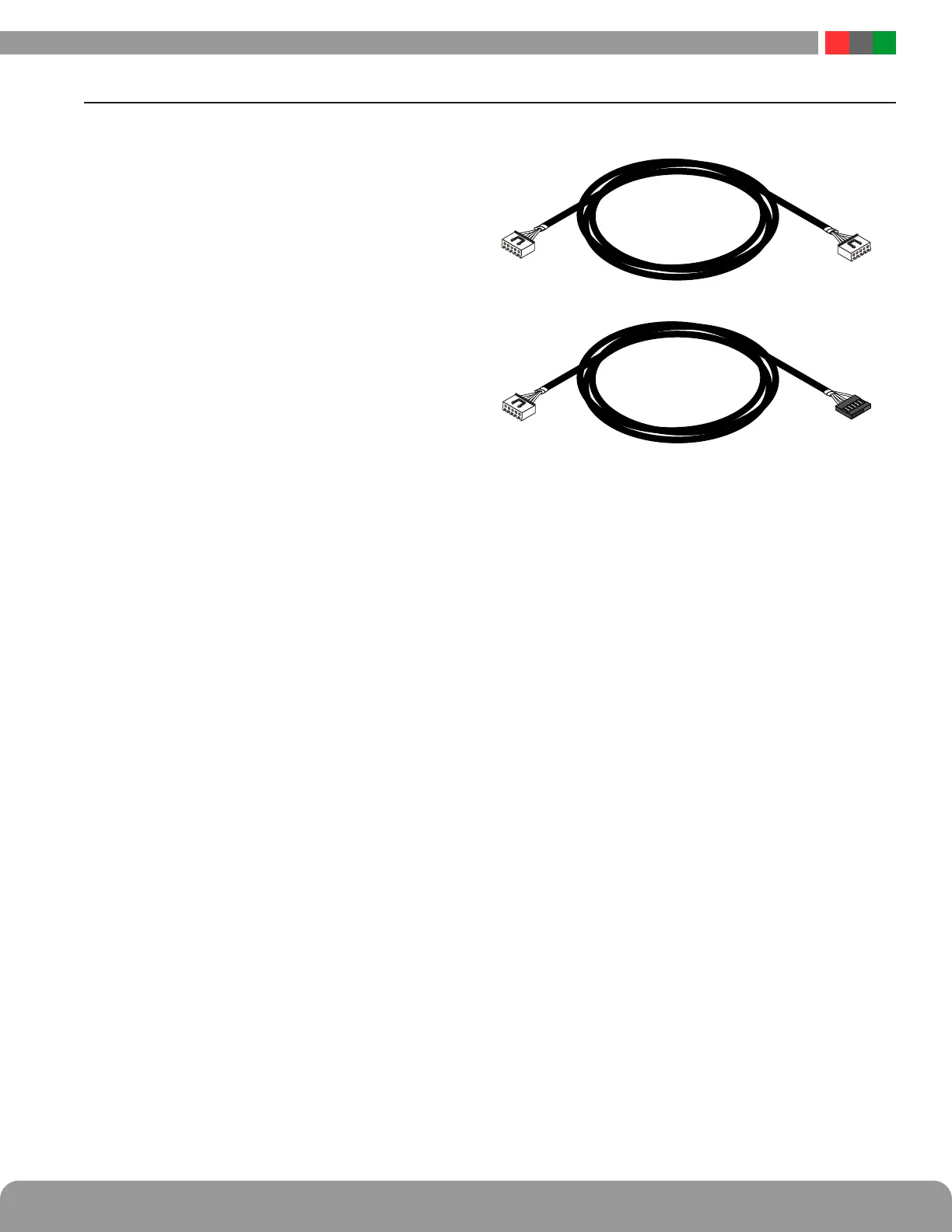
Figure 1.3 - The SPI Cable
There are two types of SPI connector which have been
used. (Figure 1.3) The Netlink is supplied with two SPI
cables for use with the new-style connector (top drawing in
Figure 1.3, above). If the device being connected to the Net-
link uses the old-style connector, contact LifeSafety Power
for an adaptor cable (bottom drawing in Figure 1.3, above).
If monitoring the battery health of FPO power supplies us-
ing the Current Sensors, the Netlink will assign Current
Sensor 1 to the FPO power supply connected to Device 1.
Current Sensor 2 will be assigned to Device 2, etc.
i Note: The NL2 can accommodate any combination of a
maximum of two power supply boards.
i Note: The NL4 can accommodate any combination of
a maximum of two power supply boards and three M8
boards.
i Note: The NLX can accommodate any combination of
a maximum of four power supply boards and seven M8
boards connected to the SPI ports.
1.3 Connecting the Netlink Network Communication Module

 Loading...