Netlink Installation and Operation Manual
4 5
Installation and Operation
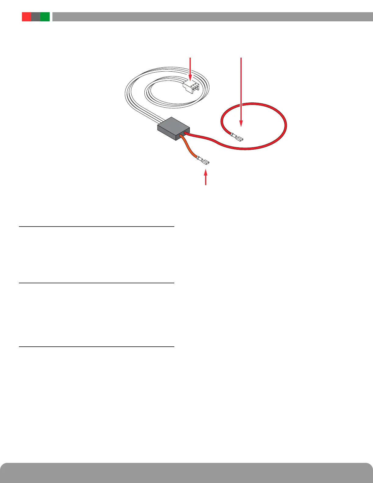
Current Sensor Cable
17 Current Sensor - Current Lead 1 (Short)
The short orange lead connects in-line with the current to
be measured toward the more negative side of the current
flow. Positive current is measured when current flows from
Current Lead 2 (Long Lead) to Current Lead 1 (Short Lead).
When using to measure battery discharge current, this lead
goes to the positive battery terminal. See section 1.3.4
18 Current Sensor - Current Lead 2 (Long)
The long red lead connects in-line with the current to be mea-
sured toward the more positive side of the current flow. Posi-
tive current is measured when current flows from Current
Lead 2 (Long Lead) to Current Lead 1 (Short Lead). When
using to measure battery discharge current, this lead goes
toward the BAT+ terminal on the power supply. See section
1.3.4
19 Current Sensor - Data Connector
This connector connects to the Netlink board's C1-C4 input
(H1 or H2 on Gen 1 boards) to provide the current reading to
the Netlink. See section 1.3.4

 Loading...