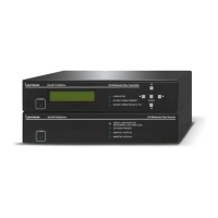
9. Technologies DVI-OPT-220-Pro series – User's Manual 35
Serial Management
General Information
There are two types of devices in general serial communication:
▪ Data Terminal Equipment: Data Terminal Equipment (DTE) is an end instrument that converts user
information into signals or reconverts received signals. Typical DTE devices: computers, LCD touch
panels and control systems.
▪ Data Circuit-terminating Equipment: Data Circuit-terminating Equipment (DCE) is a device that sits
between the DTE and a data transmission circuit. It is also called data communication equipment and
Among others the pin assignment is different between DTE and DCE.
DTE DCE
Pin 2:
RD TD
Pin 3:
TD RD
RD: Received Data (digital input)
TD: Transmitted Data (digital output)
Different type of serial cables must be used between different serial devices.
DTE DCE
DTE
Null-modem Straight
DCE
Straight Null-modem*
* In general contact DCE with DCE by tail-circuit serial cable.
Types of Serial Cables
Straight Serial Cable Null-modem Serial Cable
Straight pin-outs both ends.
Straight pin-out at the one end and cross
pin-out at the other end (interchange lines
of TX and RX).
Serial cables between devices may have male or female plugs and their type may be straight or null-modem
in usual.
ATTENTION! The cable type does not depend on the plug type.
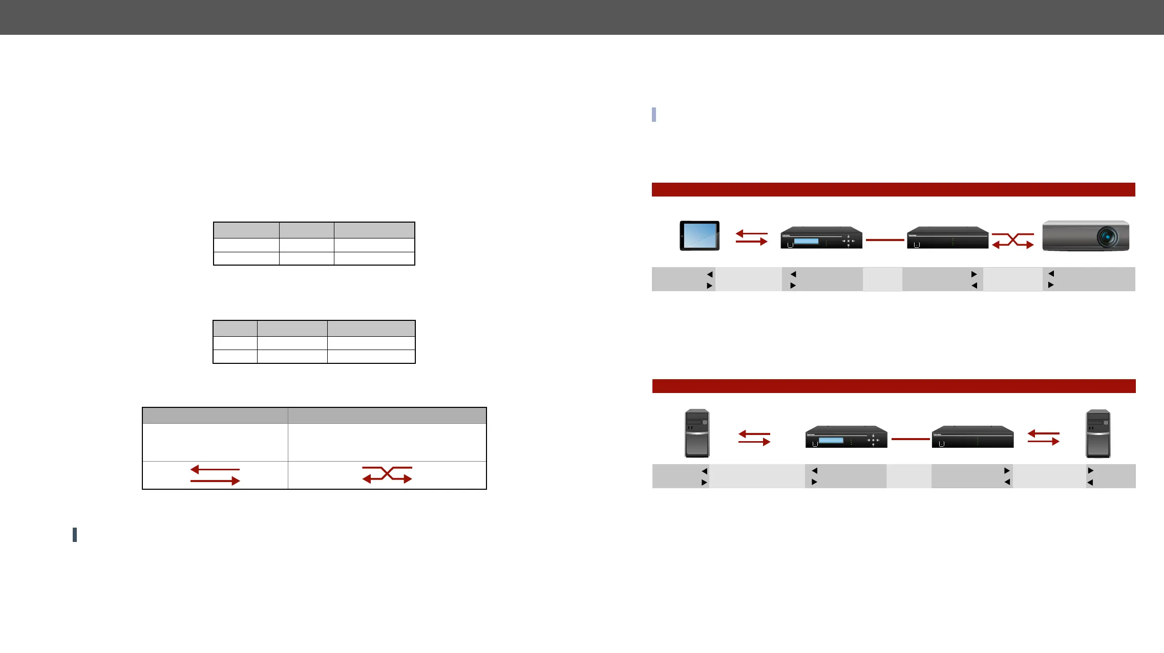
RS-232 Signal Transmission over Lightware Extender Devices
The following examples describe the detailed integration of Lightware devices between different RS-232 pin
assignment units.
INFO: DVI-OPT-220-Pro series extenders are DCE units (according to their pinouts) with female plugs.
Extending RS-232 between DTE and DCE Third-party Devices
Connect straight serial cable between controller system (DTE) and the transmitter (DCE) and null-modem
serial cable between receiver (DCE) and projector (DCE).
RS-232 Connection Example between a Controller System and a Projector
Extending RS-232 between DTE and DTE Third-party Devices
Connect straight serial cable between controller system (DTE) and the transmitter (DTE) and straight serial
serial cable between receiver (DTE) and computer (DTE).
RS-232 Connection Example between Two Computers
Transmitter
Controller system
Projector
Female - Male
Male - Male
Transmission
interface
Straight serial
cable
Null-modem
serial cable
DCE
Pin 2: RD
Pin 3: TD
Receiver
DCE
Pin 2: TD
Pin 3: RD
Pin 2: TD
Pin 3: RD
DTE
DCE
Pin 2: TD
Pin 3: RD
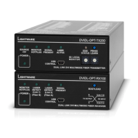
POWER
SOURCE CONNECTED (pin14 +5V)
LASER ACTIVE
DVI INPUT SIGNAL PRESENT ENTER
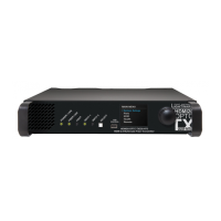
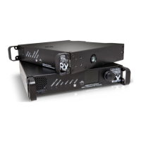
DVI Multimode Fiber TransmitterDVI-OPT-TX220-Pro
DVI Multimode Fiber Receiver
DVI-OPT-RX220-ST-Pro
MONITOR 2 HOTPLUG
DVI SIGNAL PRESENT
MONITOR 1 HOTPLUG
GREEN: LASER DETECTED
RED BLINKING: LOW LASER LEVEL
POWER
TransmitterComputer
Computer
Female - Male
Male - Female
Transmission
interface
DCE
Pin 2: RD
Pin 3: TD
Receiver
DCE
DTE
DTE
Pin 2: RD
Pin 3: TD
Pin 2: TD
Pin 3: RD
Pin 2: TD
Pin 3: RD
Straight serial
cable
Straight serial
cable
POWER
SOURCE CONNECTED (pin14 +5V)
LASER ACTIVE
DVI INPUT SIGNAL PRESENT ENTER
DVI Multimode Fiber TransmitterDVI-OPT-TX220-Pro
DVI Multimode Fiber Receiver
DVI-OPT-RX220-ST-Pro
MONITOR 2 HOTPLUG
DVI SIGNAL PRESENT
MONITOR 1 HOTPLUG
GREEN: LASER DETECTED
RED BLINKING: LOW LASER LEVEL
POWER